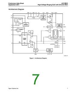
L9216B/H
Preliminary Data Sheet
September 2001
High-Voltage Ringing SLIC with Ground Start
On-Hook Transmission—Reverse Battery
State Definitions
■ Pin PR is positive with respect to PT.
Forward Active
■ VBAT1 is applied to tip/ring drive amplifiers.
■ Pin PT is positive with respect to PR.
■ Supervision circuits, loop closure, and common-
mode detect are active.
■ VBAT2 is applied to tip/ring drive amplifiers.
■ Loop closure and common-mode detect are active.
■ Ring trip detector is turned off to conserve power.
■ Ring trip detector is turned off to conserve power.
■ On-hook transmission is allowed.
■ Overhead is set to nominal 6.0 V for undistorted
transmission of 3.14 dBm into 900 Ω.
■ The tip-to-ring on-hook differential voltage will be typ-
ically between –41 V and –49 V with a –85 V primary
battery.
Reverse Active
Disconnect
■ Pin PR is positive with respect to PT.
■ The tip/ring amplifiers and all supervision are turned
■ VBAT2 is applied to tip/ring drive amplifiers.
■ Loop closure and common-mode detect are active.
■ Ring trip detector is turned off to conserve power
off.
■ The SLIC goes into a high-impedance state.
■ NSTAT is forced high (on-hook).
■ Overhead is set to nominal 6.0 V for undistorted
transmission of 3.14 dBm into 900 Ω.
■ Device will power up in this state.
Ring
Scan
■ Power ring signal is applied to tip and ring.
■ Input waveform at RINGIN is amplified.
■ Except for loop closure, all circuits (including ring trip
and common-mode detector) are powered down.
■ On-hook transmission is disabled.
■ Ring trip supervision and common-mode current
supervision are active; loop closure is inactive.
■ Pin PT is positive with respect to PR, and VBAT1 is
applied to tip/ring.
■ Overhead voltage is reduced to typically 4 V.
■ The tip to ring on-hook differential voltage will be typ-
ically between –44 V and –51 V with a –85 V primary
battery.
■ Current is limited by saturation current of the amplifi-
ers themselves, typically 100 mA at 125 °C.
Ground Start
On-Hook Transmission—Forward Battery
■ Tip drive amplifer is turned off.
■ Pin PT is positive with respect to PR.
■ Device presents a high impedance (>100 kΩ) to pin
PT.
■ VBAT1 is applied to tip/ring drive amplifiers.
■ Supervision circuits, loop closure, and common-
mode detect are active.
■ Device presents a clamped (<56.5 V) current-limited
battery (VBAT1) to PR.
■ Ring trip detector is turned off to conserve power.
■ On-hook transmission is allowed.
■ Output pin RGDET indicates current flowing in the
ring lead.
■ The tip-to-ring on-hook differential voltage will be typ-
ically between –41 V and –49 V with a –85 V primary
battery.
Thermal Shutdown
■ Not controlled via truth table inputs.
■ NSTAT is forced low (off-hook) during this state
■ This mode is caused by excessive heating of the
device, such as may be encountered in an extended
power-cross situation.
10
Agere Systems Inc.

 ZARLINK [ ZARLINK SEMICONDUCTOR INC ]