R
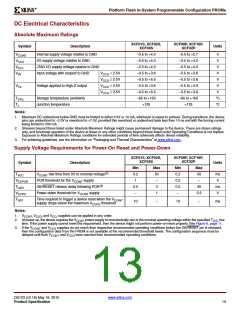
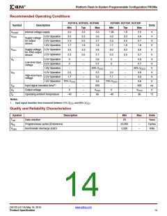
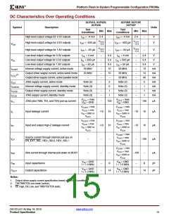
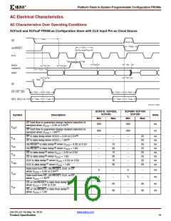
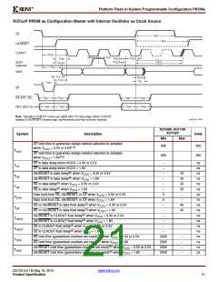
Platform Flash In-System Programmable Configuration PROMs
XCF01S, XCF02S,
XCF04S
XCF08P, XCF16P,
XCF32P
Symbol
Description
Units
Min
30
67
–
Max
–
Min
25
25
30
30
12
12
12
12
Max
–
Clock period(6) (serial mode) when VCCO = 3.3V or 2.5V
Clock period(6) (serial mode) when VCCO = 1.8V
Clock period(6) (parallel mode) when VCCO = 3.3V or 2.5V
Clock period(6) (parallel mode) when VCCO = 1.8V
CLK Low time(3) when VCCO = 3.3V or 2.5V
CLK Low time(3) when VCCO = 1.8V
ns
ns
ns
ns
ns
ns
ns
ns
–
–
TCYC
–
–
–
–
–
10
15
10
15
–
–
TLC
–
–
CLK High time(3) when VCCO = 3.3V or 2.5V
CLK High time(3) when VCCO = 1.8V
–
–
THC
–
–
CE setup time to CLK (guarantees proper counting)(3)
when VCCO = 3.3V or 2.5V
CE setup time to CLK (guarantees proper counting)(3)
when VCCO = 1.8V
CE hold time (guarantees counters are reset)(5)
when VCCO = 3.3V or 2.5V
CE hold time (guarantees counters are reset)(5)
when VCCO = 1.8V
OE/RESET hold time (guarantees counters are reset)(6)
when VCCO = 3.3V or 2.5V
OE/RESET hold time (guarantees counters are reset)(6)
when VCCO = 1.8V
20
–
30
–
–
–
–
–
–
ns
ns
ns
ns
ns
ns
TSCE
THCE
THOE
30
30
250
250
250
250
–
–
–
–
2000
2000
2000
2000
BUSY setup time to CLK when VCCO = 3.3V or 2.5V(8)
BUSY setup time to CLK when VCCO = 1.8V(8)
BUSY hold time to CLK when VCCO = 3.3V or 2.5V(8)
BUSY hold time to CLK when VCCO = 1.8V(8)
–
–
–
–
–
–
–
–
12
12
8
–
–
–
–
ns
ns
ns
ns
TSB
THB
8
EN_EXT_SEL setup time to CF, CE or OE/RESET
when VCCO = 3.3V or 2.5V(8)
–
–
–
–
–
–
–
–
–
–
–
–
–
–
–
–
300
300
300
300
300
300
300
300
–
–
–
–
–
–
–
–
ns
ns
ns
ns
ns
ns
ns
ns
TSXT
THXT
TSRV
EN_EXT_SEL setup time to CF, CE or OE/RESET
when VCCO = 1.8V(8)
EN_EXT_SEL hold time from CF, CE or OE/RESET
when VCCO = 3.3V or 2.5V(8)
EN_EXT_SEL hold time from CF, CE or OE/RESET
when VCCO = 1.8V(8)
REV_SEL setup time to CF, CE or OE/RESET
when VCCO = 3.3V or 2.5V(8)
REV_SEL setup time to CF, CE or OE/RESET
when VCCO = 1.8V(8)
REV_SEL hold time from CF, CE or OE/RESET
when VCCO = 3.3V or 2.5V(8)
THRV
REV_SEL hold time from CF, CE or OE/RESET
when VCCO = 1.8V(8)
Notes:
1. AC test load = 50 pF for XCF01S/XCF02S/XCF04S; 30 pF for XCF08P/XCF16P/XCF32P.
2. Float delays are measured with 5 pF AC loads. Transition is measured at 200 mV from steady-state active levels.
3. All AC parameters are measured with V = 0.0V and V = 3.0V.
IL
IH
4. If T
5. If T
High < 2 µs, T = 2 µs.
HCE
CE
Low < 2 µs, T = 2 µs.
HOE
OE
6. This is the minimum possible T
3.3V, if FPGA data setup time = 15 ns, then the actual T
7. Guaranteed by design; not tested.
. Actual T
= T
+ FPGA Data setup time. Example: With the XCF32P in serial mode with V
CCO
CYC
at
CYC
CYC
CAC
= 25 ns +15 ns = 40 ns.
8. CF, EN_EXT_SEL, REV_SEL[1:0], and BUSY are inputs for the XCFxxP PROM only.
9. When JTAG CONFIG command is issued, PROM drives CF Low for at least the T
minimum.
HCF
DS123 (v2.18) May 19, 2010
www.xilinx.com
Product Specification
17

 XILINX [ XILINX, INC ]