X24C01
A.C. CHARACTERISTICS (Over recommended operating conditions, unless otherwise specified)
Read & Write Cycle Limits
Symbol
Parameter
Min.
Max.
Units
f
SCL Clock Frequency
0
100
100
KHz
ns
SCL
T
Noise Suppression Time
I
Constant at SCL, SDA Inputs
t
t
SCL Low to SDA Data Out Valid
0.3
4.7
3.5
µs
µs
AA
Time the Bus Must Be Free Before a
New Transmission Can Start
BUF
t
t
t
t
t
t
t
t
t
t
Start Condition Hold Time
Clock Low Period
4.0
4.7
4.0
4.7
0
µs
µs
µs
µs
µs
ns
µs
ns
µs
ns
HD:STA
LOW
Clock High Period
HIGH
SU:STA
HD:DAT
SU:DAT
R
Start Condition Setup Time
Data In Hold Time
Data In Setup Time
250
SDA and SCL Rise Time
SDA and SCL Fall Time
Stop Condition Setup Time
Data Out Hold Time
1
300
F
4.7
SU:STO
DH
300
3837 PGM T06
POWER-UP TIMING
Symbol
Parameter
Max.
Units
(4)
t
t
Power-up to Read Operation
Power-up to Write Operation
1
5
ms
ms
PUR
(4)
PUW
3837 PGM T07
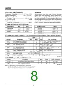
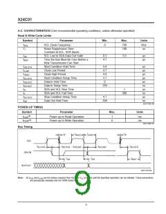
Bus Timing
t
t
t
t
HIGH
LOW
R
F
SCL
t
t
t
t
t
SU:STO
SU:STA
HD:STA
HD:DAT
SU:DAT
SDA IN
t
t
t
BUF
AA
DH
SDA OUT
3837 FHD F04
Note: (4) t
and t
are the delays required from the time V is stable until the specified operation can be initiated. These parameters
PUW CC
PUR
are periodically sampled and not 100% tested.
9

 XICOR [ XICOR INC. ]