Product Preview
WM8983
INPUT SIGNAL PATH
The WM8983 has a number of flexible analogue inputs. There are two input channels, Left and
Right, each of which consists of an input PGA stage followed by a boost/mix stage which drives into
the hi-fi ADC. Each input path has three input pins which can be configured in a variety of ways to
accommodate single-ended, differential or dual differential microphones. There are two auxiliary
input pins which can be fed into to the input boost/mix stage as well as driving into the output path.
A bypass path exists from the output of the boost/mix stage into the output left/right mixers.
MICROPHONE INPUTS
The WM8983 can accommodate a variety of microphone configurations including single ended and
pseudo differential inputs. The inputs to the left pseudo differential input PGA are LIP and L2. The
inputs to the right pseudo differential input PGA are RIP and R2. LIN and RIN are used for a.c.
coupled ground inputs.
In single-ended microphone input configuration the microphone signal should be input to LIN or RIN
and the non-inverting input of the input PGA clamped to VMID.
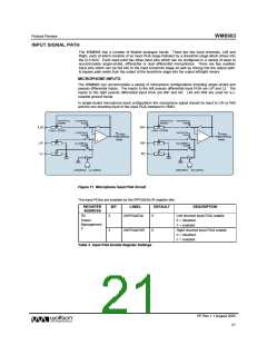
Figure 11 Microphone Input PGA Circuit
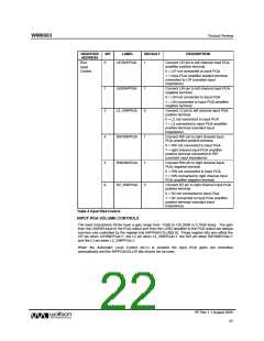
The input PGAs are enabled by the IPPGAENL/R register bits.
REGISTER
ADDRESS
BIT
LABEL
DEFAULT
DESCRIPTION
R2
2
3
INPPGAENL
0
0
Left channel input PGA enable
0 = disabled
Power
Management
2
1 = enabled
INPPGAENR
Right channel input PGA enable
0 = disabled
1 = enabled
Table 3 Input PGA Enable Register Settings
PP Rev 1.1 August 2005
21
w

 WOLFSON [ WOLFSON MICROELECTRONICS PLC ]