Pre-Production
WM8976
REGISTER
ADDRESS
BIT
LABEL
DEFAULT
DESCRIPTION
0000
0001
0010
22.7us 182.4us 1.31ms
45.4us
90.8us
363us
726us
2.62ms
5.23ms
… (time doubles with every step)
1010
or
23.2ms
186ms 1.34s
higher
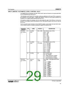
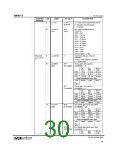
Table 17 ALC Control Registers
When the ALC is disabled, the input PGA remains at the last controlled value of the ALC. An input
gain update must be made by writing to the INPPGAVOLL/R register bits.
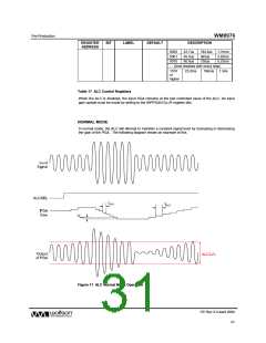
NORMAL MODE
In normal mode, the ALC will attempt to maintain a constant signal level by increasing or decreasing
the gain of the PGA. The following diagram shows an example of this.
Figure 11 ALC Normal Mode Operation
PP Rev 3.0 April 2006
31
w

 WOLFSON [ WOLFSON MICROELECTRONICS PLC ]