Pre-Production
WM8959
These registers are described in Table 50 below.
REGISTER
ADDRESS
BIT
LABEL
DEFAULT
DESCRIPTION
R8 (08h)
15
AIF_MSTR1
0b
Audio Interface 1 Master Mode Select
0 = Slave mode
1 = Master mode
14
13
AIF_MSTR2
AIF_SEL
0b
0b
Audio Interface 2 Master Mode Select
0 = Slave mode
1 = Master mode
Audio Interface Select
0 = Audio interface 1
1 = Audio interface 2 (GPIO3/BCLK2,
GPIO4/DACLRC2, GPIO5/DACDAT2)
R9 (09h)
11
DACLRC_DIR
0b
DACLRC Direction
(Forces DACLRC clock to be output in
slave mode)
0 = DACLRC normal operation
1 = DACLRC clock output enabled
Table 50 Audio Interface Output Function Control
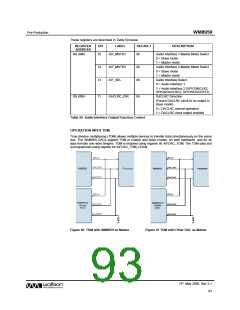
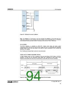
OPERATION WITH TDM
Time division multiplexing (TDM) allows multiple devices to transfer data simultaneously on the same
bus. The WM8959 DACs support TDM in master and slave modes, on both interfaces, and for all
data formats and word lengths. TDM is enabled using register bit AIFDAC_TDM. The TDM data slot
is programmed using register bit AIFDAC_TDM_CHAN.
BCLK
DACLRC
WM8959
Processor
DACDAT
BCLK
WM8959 or
Similar
DAC
DACLRC
DACDAT
Figure 60 TDM with WM8959 as Master
Figure 61 TDM with Other DAC as Master
PP, May 2008, Rev 3.1
93
w

 WOLFSON [ WOLFSON MICROELECTRONICS PLC ]