Pre-Production
WM8959
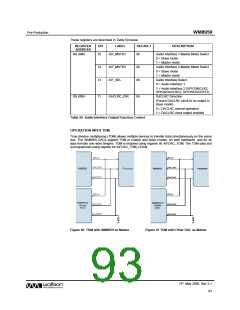
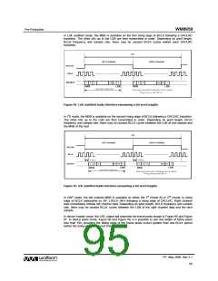
In Left Justified mode, the MSB is available on the first rising edge of BCLK following a DACLRC
transition. The other bits up to the LSB are then transmitted in order. Depending on word length,
BCLK frequency and sample rate, there may be unused BCLK cycles before each DACLRC
transition.
Figure 64 Left Justified Audio Interface (assuming n-bit word length)
In I2S mode, the MSB is available on the second rising edge of BCLK following a DACLRC transition.
The other bits up to the LSB are then transmitted in order. Depending on word length, BCLK
frequency and sample rate, there may be unused BCLK cycles between the LSB of one sample and
the MSB of the next.
Figure 65 I2S Justified Audio Interface (assuming n-bit word length)
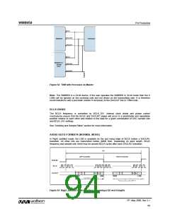
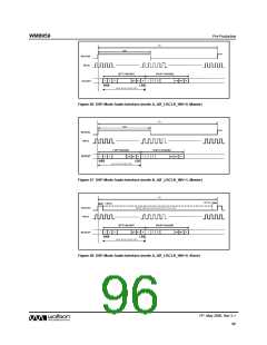
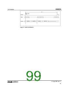
In DSP mode, the left channel MSB is available on either the 1st (mode B) or 2nd (mode A) rising
edge of BCLK (selectable by AIF_LRCLK_INV) following a rising edge of DACLRC. Right channel
data immediately follows left channel data. Depending on word length, BCLK frequency and sample
rate, there may be unused BCLK cycles between the LSB of the right channel data and the next
sample.
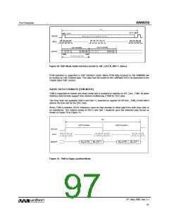
In device master mode, the LRC output will resemble the frame pulse shown in Figure 66 and Figure
67. In device slave mode, Figure 68 and Figure 69, it is possible to use any length of frame pulse
less than 1/fs, providing the falling edge of the frame pulse occurs greater than one BCLK period
before the rising edge of the next frame pulse.
PP, May 2008, Rev 3.1
95
w

 WOLFSON [ WOLFSON MICROELECTRONICS PLC ]