Pre-Production
WM8959
DIGITAL AUDIO INTERFACE
The digital audio interface is used for inputting DAC data to the WM8959. It uses three pins:
•
•
•
DACDAT: DAC data input
DACLRC: DAC data alignment clock
BCLK: Bit clock, for synchronisation
DACDAT, DACLRC and BCLK functions can also be supported using alternative GPIO pins.
The clock signals BCLK and DACLRC can be outputs when the WM8959 operates as a master, or
inputs when it is a slave (see Master and Slave Mode Operation, below).
Four different audio data formats are supported:
•
•
•
•
Left justified
Right justified
I2S
DSP mode
All four of these modes are MSB first. They are described in Audio Data Formats, below. Refer to the
“Electrical Characteristics” section for timing information.
Time Division Multiplexing (TDM) is available in all four data format modes. The WM8959 can be
programmed to send and receive data in one of two time slots.
PCM operation is supported using the DSP mode.
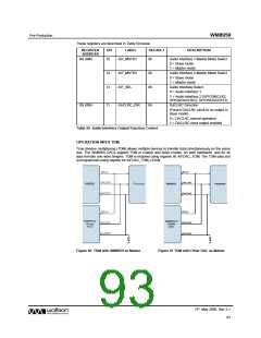
MASTER AND SLAVE MODE OPERATION
The WM8959 digital audio interface can operate as a master or slave as shown in Figure 50 and
Figure 51.
Figure 50 Master Mode
Figure 51 Slave Mode
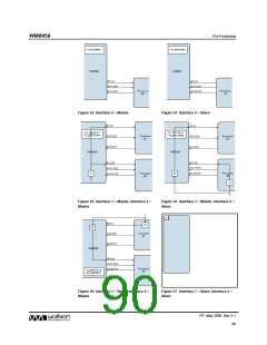
OPERATION WITH ALTERNATIVE DAC INTERFACE
To allow data to be input to the WM8959 DACs from two separate sources, the GPIO[5:3] pins can
be configured as an alternative DAC interface (BCLK2, DACLRC2, DACDAT2) as shown in Figure 52
to Figure 57.
PP, May 2008, Rev 3.1
89
w

 WOLFSON [ WOLFSON MICROELECTRONICS PLC ]