WM8959
Pre-Production
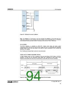
BCLK
DACLRC
DACDAT
WM8959
Processor
BCLK
WM8959 or
Similar
DAC
DACLRC
DACDAT
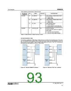
Figure 62 TDM with Processor as Master
Note: The WM8959 is a 24-bit device. If the user operates the WM8959 in 32-bit mode then the 8
LSBs will be ignored on the receiving side and not driven on the transmitting side. It is therefore
recommended to add a pull-down resistor if necessary to the DACDAT line in TDM mode.
BCLK DIVIDE
The BCLK frequency is controlled by BCLK_DIV. Internal clock divide and phase control
mechanisms ensure that the BCLK and DACLRC edges will occur in a predictable and repeatable
position relative to each other and relative to the data for a given combination of DAC sample rate
and BCLK_DIV settings.
See “Clocking and Sample Rates” section for more information.
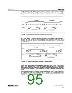
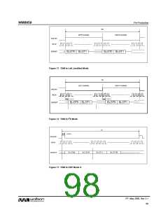
AUDIO DATA FORMATS (NORMAL MODE)
In Right Justified mode, the LSB is available on the last rising edge of BCLK before a DACLRC
transition. All other bits are transmitted before (MSB first). Depending on word length, BCLK
frequency and sample rate, there may be unused BCLK cycles after each DACLRC transition.
Figure 63 Right Justified Audio Interface (assuming n-bit word length)
PP, May 2008, Rev 3.1
94
w

 WOLFSON [ WOLFSON MICROELECTRONICS PLC ]