Pre-Production
WM8959
MASTER MODE BCLK AND DACLRC ENABLE
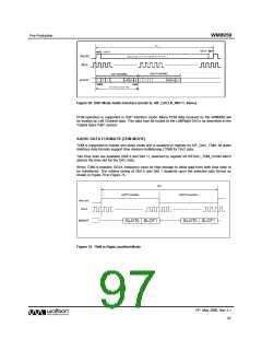
The main audio interface pins (BCLK, DACLRC and DACDAT) and the alternative interface pins
(BCLK2, DACLRC2, DACDAT2) can be independently programmed to operate in master mode or
slave mode using register bits AIF_MSTR1 and AIF_MSTR2.
When the main audio interface is operating in slave mode, the BCLK and DACLRC clock outputs to
these pins are by default disabled to allow the digital audio source to drive these pins. Similarly,
when the alternative audio interface is operating in slave mode, the BCLK2 and DACLRC2 clock
outputs to these pins are by default disabled.
It is possible to force the DACLRC or DACLRC2 to be output using register bit DACLRC_DIR,
allowing mixed master and slave modes on the active audio interface. The active audio interface is
selected by register bit AIF_SEL. Enabled clock outputs on the de-selected audio interface will output
logic 0.
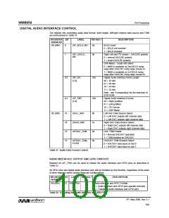
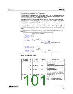
The clock generators for the audio interface are enabled according to the control signals shown in
Figure 75.
Figure 75 Clock Output Control
REGISTER
ADDRESS
BIT
LABEL
DEFAULT
DESCRIPTION
R8 (08h)
15
AIF_MSTR1
0b
Audio Interface 1 Master Mode Select
0 = Slave mode
1 = Master mode
14
13
AIF_MSTR2
AIF_SEL
0b
0b
Audio Interface 2 Master Mode Select
0 = Slave mode
1 = Master mode
Audio Interface Select
0 = Audio interface 1
1 = Audio interface 2 (GPIO3/BCLK2,
GPIO4/DACLRC2, GPIO5/DACDAT2)
R9 (09h)
11
DACLRC_DIR
0b
DACLRC Direction
(Forces DACLRC clock to be output in
slave mode)
0 = DACLRC normal operation
1 = DACLRC clock output enabled
PP, May 2008, Rev 3.1
101
w

 WOLFSON [ WOLFSON MICROELECTRONICS PLC ]