WM8959
Pre-Production
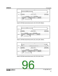
DIGITAL AUDIO INTERFACE CONTROL
The register bits controlling audio data format, word length, left/right channel data source and TDM
are summarised in Table 51.
REGISTER BIT
ADDRESS
LABEL
DEFAULT
DESCRIPTION
R4 (04h)
8
AIF_BCLK_INV
0b
BCLK Invert
0 = BCLK not inverted
1 = BCLK inverted
7
AIF_LRCLK_
INV
0b
Right, left and I2S modes – DACLRC polarity
0 = normal DACLRC polarity
1 = invert DACLRC polarity
DSP Mode – mode A/B select
0 = MSB is available on 2nd BCLK rising
edge after DACLRC rising edge (mode A)
1 = MSB is available on 1st BCLK rising
edge after DACLRC rising edge (mode B)
6:5
AIF_WL
[1:0]
10b
Digital Audio Interface Word Length
00 = 16 bits
01 = 20 bits
10 = 24 bits
11 = 32 bits
Note - see “Companding” for the selection of
8-bit mode
4:3
AIF_FMT
[1:0]
10b
Digital Audio Interface Format
00 = Right justified
01 = Left justified
10 = I2S Format
11 = DSP Mode
R5 (05h)
15
14
12
13
DACL_SRC
DACR_SRC
AIFDAC_TDM
0b
1b
0b
0b
Left DAC Data Source Select
0 = Left DAC outputs left channel data
1 = Left DAC outputs right channel data
Right DAC Data Source Select
0 = Right DAC outputs left channel data
1 = Right DAC outputs right channel data
DAC TDM Enable
0 = Normal DACDAT operation
1 = TDM enabled on DACDAT
DACDAT TDM Channel Select
0 = DACDAT data input on slot 0
1 = DACDAT data input on slot 1
AIFDAC_TDM_
CHAN
Table 51 Audio Data Format Control
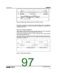
AUDIO INTERFACE OUTPUT AND GPIO TRISTATE
Register bit AIF_TRIS can be used to tristate the audio interface and GPIO pins as described in
Table 52.
All GPIO pins and digital audio interface pins will be tristated by this function, regardless of the state
of other registers which control these pin configurations.
REGISTER BIT
ADDRESS
LABEL DEFAULT
DESCRIPTION
R9 (09h)
13 AIF_TRIS
0
Audio Interface and GPIO Tristate
0 = Audio interface and GPIO pins operate normally
1 = Tristate all audio interface and GPIO pins
Table 52 Tri-stating the Audio Interface and GPIO Pins
PP, May 2008, Rev 3.1
100
w

 WOLFSON [ WOLFSON MICROELECTRONICS PLC ]