Pre-Production
WM8904
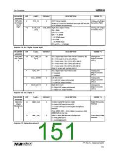
REGISTER
ADDRESS
BIT
LABEL
DEFAULT
DESCRIPTION
REFER TO
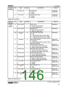
DAC TDM Enable
Digital Audio
Interface Control
R25 (19h)
Audio
Interface 1
13
AIFDAC_TDM
0
0 = Normal DACDAT operation
1 = TDM enabled on DACDAT
DACDAT TDM Channel Select
0 = DACDAT data input on slot 0
1 = DACDAT data input on slot 1
ADC TDM Enable
Digital Audio
Interface Control
12
11
10
8
AIFDAC_TDM_
CHAN
0
0
0
0
0
0
0
Digital Audio
Interface Control
AIFADC_TDM
0 = Normal ADCDAT operation
1 = TDM enabled on ADCDAT
ADCDAT TDM Channel Select
0 = ADCDAT outputs data on slot 0
1 = ADCDAT output data on slot 1
Audio Interface Tristate
Digital Audio
Interface Control
AIFADC_TDM_
CHAN
Digital Audio
Interface Control
AIF_TRIS
AIF_BCLK_INV
BCLK_DIR
0 = Audio interface pins operate normally
1 = Tristate all audio interface pins
BCLK Invert
Digital Audio
Interface Control
7
0 = BCLK not inverted
1 = BCLK inverted
Audio Interface BCLK Direction
0 = BCLK is input
Digital Audio
Interface Control
6
1 = BCLK is output
LRC Polarity / DSP Mode A-B select.
Digital Audio
Interface Control
4
AIF_LRCLK_IN
V
Right, left and I2S modes – LRC polarity
0 = Not Inverted
1 = Inverted
DSP Mode – Mode A-B select
0 = MSB is available on 2nd BCLK rising edge after
LRC rising edge (mode A)
1 = MSB is available on 1st BCLK rising edge after LRC
rising edge (mode B)
Digital Audio Interface Word Length
00 = 16 bits
Digital Audio
Interface Control
3:2
1:0
AIF_WL [1:0]
AIF_FMT [1:0]
10
10
01 = 20 bits
10 = 24 bits
11 = 32 bits
Digital Audio Interface Format
00 = Right Justified
01 = Left Justified
10 = I2S
Digital Audio
Interface Control
11 = DSP
Register 19h Audio Interface 1
PP, Rev 3.3, September 2012
147
w

 WOLFSON [ WOLFSON MICROELECTRONICS PLC ]