Production Data
WM8805
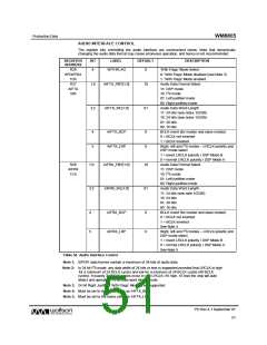
AUDIO INTERFACE CONTROL
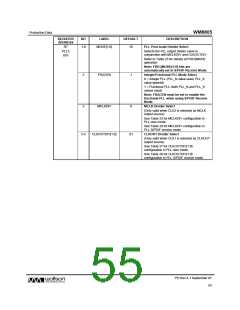
The register bits controlling the audio interface are summarised below. Note that dynamically
changing the audio data format may cause erroneous operation, and hence is not recommended.
REGISTER
ADDRESS
BIT
LABEL
DEFAULT
DESCRIPTION
R29
SPDIFRX1
1Dh
4
WITHFLAG
0
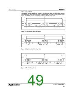
‘With Flags’ Mode Select
0: ‘With Flags’ Mode disabled (see Note 3)
1: ‘With Flags’ Mode enabled
Audio Data Format Select
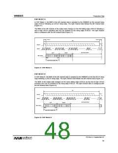
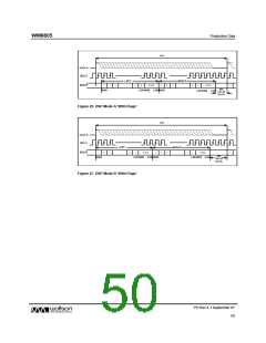
11: DSP mode
R27
1:0
3:2
AIFTX_FMT[1:0]
AIFTX_WL[1:0]
10
01
AIFTX
1Bh
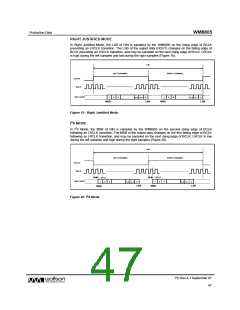
10: I2S mode
01: Left justified mode
00: Right justified mode
Audio Data Word Length
11: 24 bits (see notes 1/2/3/6)
10: 24 bits (see notes 1/2/3/6)
01: 20 bits
00: 16 bits
4
5
AIFTX_BCP
AIFTX_LRP
0
0
BCLK invert (for master and slave modes)
0 = BCLK not inverted
1 = BCLK inverted
Right, left and I2S modes – LRCLK polarity and
DSP mode select
1 = invert LRCLK polarity / DSP Mode B
0 = normal LRCLK polarity / DSP Mode A
Audio Data Format Select
11: DSP mode
R28
AIFRX
1Ch
1:0
3:2
AIFRX_FMT[1:0]
AIFRX_WL[1:0]
10
01
10: I2S mode
01: Left justified mode
00: Right justified mode
Audio Data Word Length
11: 24 bits (see note 1/2/3/6)
10: 24 bits
01: 20 bits
00: 16 bits
4
5
AIFRX_BCP
AIFRX_LRP
0
0
BCLK Invert (for master and slave modes)
0 = BCLK not inverted
1 = BCLK inverted
See Note 4
Right, left and I2S modes – LRCLK polarity and
DSP mode select
1 = invert LRCLK polarity / DSP Mode B
0 = normal LRCLK polarity / DSP Mode A
See Note 5
Table 56 Audio Interface Control
Note 1: S/PDIF data frames contain a maximum of 24-bits of audio data
Note 2: In 24 bit I2S mode, any data width of 24 bits or less is supported provided that LRCLK is high
for a minimum of 24 BCLK cycles and low for a minimum of 24 BCLK cycles (48 BCLK
cycles). If exactly 32 BCLK cycles occur in one LRCLK (16 high, 16 low) the chip will auto
detect and operate in 16 bit data word length mode.
Note 3: 24 bit Right Justified ‘With Flags’ Mode is not supported.
Note 4: Must be set to the same value as AIFTX_BCP.
Note 5: Must be set to the same value as AIFTX_LRP.
PD Rev 4.1 September 07
51
w

 WOLFSON [ WOLFSON MICROELECTRONICS PLC ]