Production Data
WM8352
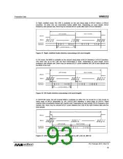
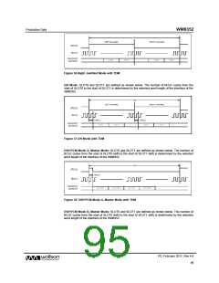
Figure 56 Right Justified Mode with TDM
I2S Mode: SLOT0 and SLOT1 are defined as shown below. The number of BCLK cycles from the
start of SLOT0 to the start of SLOT1 is determined by the selected word length of the interface of the
WM8352.
Figure 57 I2S Mode with TDM
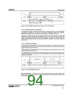
DSP/PCM Mode A, Master Mode: SLOT0 and SLOT1 are defined as shown below. The number of
BCLK cycles from the start of SLOT0 (left) to the start of SLOT1 (left) is determined by the selected
word length of the interface of the WM8352.
Figure 58 DSP/PCM Mode A, Master Mode with TDM
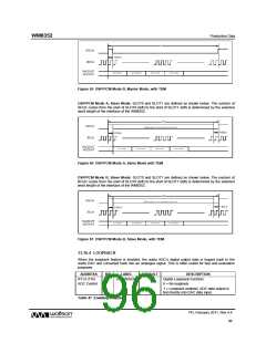
DSP/PCM Mode B, Master Mode: SLOT0 and SLOT1 are defined as shown below. The number of
BCLK cycles from the start of SLOT0 (left) to the start of SLOT1 (left) is determined by the selected
word length of the interface of the WM8352.
PD, February 2011, Rev 4.4
95
w

 WOLFSON [ WOLFSON MICROELECTRONICS PLC ]