WM8352
Production Data
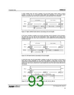
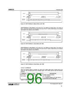
Figure 59 DSP/PCM Mode B, Master Mode, with TDM
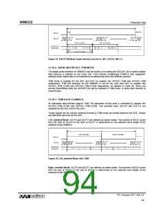
DSP/PCM Mode A, Slave Mode: SLOT0 and SLOT1 are defined as shown below. The number of
BCLK cycles from the start of SLOT0 (left) to the start of SLOT1 (left) is determined by the selected
word length of the interface of the WM8352.
Figure 60 DSP/PCM Mode A, Slave Mode with TDM
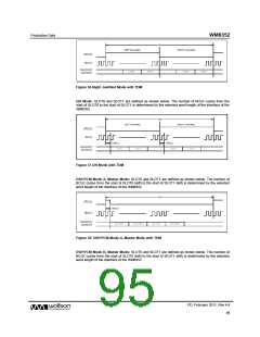
DSP/PCM Mode B, Slave Mode: SLOT0 and SLOT1 are defined as shown below. The number of
BCLK cycles from the start of SLOT0 (left) to the start of SLOT1 (left) is determined by the selected
word length of the interface of the WM8352.
Figure 61 DSP/PCM Mode B, Slave Mode, with TDM
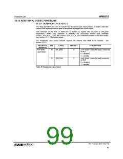
13.10.4 LOOPBACK
When the loopback feature is enabled, the audio ADC’s digital output data is looped back to the
audio DAC and converted back into an analogue signal. This is often useful for test and evaluation
purposes.
ADDRESS
R113 (71h)
ADC Control
BIT
LABEL
DEFAULT
DESCRIPTION
Digital Loopback Function
0
LOOPBACK
0
0 = No loopback.
1 = Loopback enabled, ADC data output is
fed directly into DAC data input.
Table 47 Enabling loopback
PD, February 2011, Rev 4.4
96
w

 WOLFSON [ WOLFSON MICROELECTRONICS PLC ]