WM8352
Production Data
DESCRIPTION
ADDRESS
BIT
LABEL
DEFAULT
10
8:9
AIF_FMT [1:0]
Data format
(I2S)
00 = Right Justified
01 = Left Justified
10 = I2S
11 = DSP / PCM mode
Note - see Section 13.11 for the
selection of 8-bit mode.
R114 (72h)
7
6
5
4
3
7
6
5
4
3
AIFADC_PD
0
0
1
0
0
0
0
1
0
0
Enables a pull down on ADC data pin
0 = disabled
Audio
Interface
ADC
1 = enabled
AIFADCL_SRC
AIFADCR_SRC
Selects Left channel ADC output.
0 = ADC Left channel
Control
1 = ADC Right channel
Selects Right channel ADC output.
0 = ADC Left channel
1 = ADC Right channel
AIFADC_TDM_
CHAN
ADCDAT TDM Channel Select
0 = ADCDAT outputs data on slot 0
1 = ADCDAT outputs data on slot 1
ADC TDM Enable
AIFADC_TDM
AIFDAC_PD
DACL_SRC
DACR_SRC
0 = Normal ADCDAT operation
1 = TDM enabled on ADCDAT
Enables a pull down on DAC data pin
0 = disabled
R115 (73h)
Audio
Interface
DAC
1 = enabled
Selects Left channel DAC input.
0 = DAC Left channel
Control
1 = DAC Right channel
Selects Right channel DAC input.
0 = DAC Left channel
1 = DAC Right channel
AIFDAC_TDM_
CHAN
DACDAT TDM Channel Select
0 = DACDAT outputs data on slot 0
1 = DACDAT outputs data on slot 1
DAC TDM Enable
AIFDAC_TDM
0 = Normal DACDAT operation
1 = TDM enabled on DACDAT
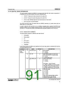
Table 46 Selecting the Audio Data Format
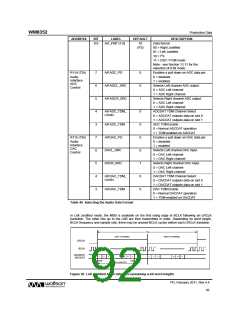
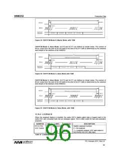
In Left Justified mode, the MSB is available on the first rising edge of BCLK following an LRCLK
transition. The other bits up to the LSB are then transmitted in order. Depending on word length,
BCLK frequency and sample rate, there may be unused BCLK cycles before each LRCLK transition.
1/fs
LEFT CHANNEL
RIGHT CHANNEL
LRCLK
BCLK
DACDAT/
ADCDAT
1
2
3
n-2
n-1
n
1
2
3
n-2
n-1
n
MSB
LSB
Input Word Length (WL)
Figure 50 Left Justified Audio Interface (assuming n-bit word length)
PD, February 2011, Rev 4.4
92
w

 WOLFSON [ WOLFSON MICROELECTRONICS PLC ]