Production Data
WM8352
A beep signal on the IN3R pin (see Table 43) can be mixed into OUT2R independently of the right
output mixer (i.e. without mixing the same beep signal into OUT1R).
Note that this feature is only possible when the inverting path configuration (MIXOUTR to OUT2R) is
selected. See Table 41 for the required register settings.
ADDRESS
BIT
LABEL
DEFAULT
DESCRIPTION
Beep mixer enable
R111 (6Fh)
15
IN3R_TO_O
UT2R
0
Beep
0 = disabled
Volume
1 = enabled
7:5
IN3R_OUT2R
_VOL [2:0]
000
Beep mixer volume:
000 = -15dB
… in +3dB steps
111 = +6dB
Table 43 Controlling the “Beep” Path (IN3R to OUT2R)
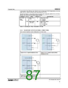
13.9.3 HEADPHONE OUTPUTS EXTERNAL CONNECTIONS
Some example headphone output configurations are shown below.
Figure 46 AC-Coupled Headphone Drive
Figure 47 DC-Coupled (Capless) Mode
Headphone Drive
Figure 48 AC-Coupled Headphone Drive
with Common Mode Noise Rejection
PD, February 2011, Rev 4.4
87
w

 WOLFSON [ WOLFSON MICROELECTRONICS PLC ]