Production Data
WM8352
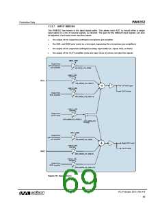
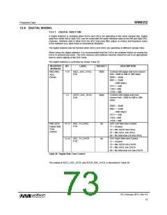
13.4.7 INPUT MIXERS
The WM8352 has mixers in the input signal paths. This allows each ADC to record either a single
input signal or a mix of several signals, as desired. The gain for the different input signals can also
be adjusted. Each input mixer has four inputs:
•
•
•
•
the output of the respective (left/right) microphone pre-amplifier
the IN2L and IN2R pins (used as a line input, bypassing the microphone pre-amplifiers)
the output of the respective (left/right) auxiliary input buffer (ie. inputs IN3L or IN3R)
the output of the OUT4 amplifier (only one input mixer at a time can take this signal)
0dB or +20dB
Output from
left microphone
pre-amplifier
INL_MIXINL_VOL, R98[0]
-12dB to + 6dB
and mute
IN2L
IN2L_MIXINL_VOL, R98[3:1]
Left ADC input
OUT3 mixer
-1
-12dB to + 6dB,
and mute
Output from
IN3L amplifier
IN3L_MIXINL_VOL, R98[11:9]
-12dB to + 6dB
and mute
Output from
OUT4 mixer
OUT4_MIXIN_VOL, R100[3:1]
OUT4_MIXIN_DST,
R100[15]
0dB or +20dB
Output from
right microphone
pre-amplifier
INR_MIXINR_VOL, R99[0]
Right ADC input
OUT4 mixer
-1
-12dB to + 6dB
and mute
INR2
INR2_MIXINR_VOL, R99[7:5]
-12dB to + 6dB,
and mute
Output from
IN3R amplifier
IN3R_MIXINR_VOL, R99[15:13]
Figure 39 Input Mixers
PD, February 2011, Rev 4.4
69
w

 WOLFSON [ WOLFSON MICROELECTRONICS PLC ]