WM8352
Production Data
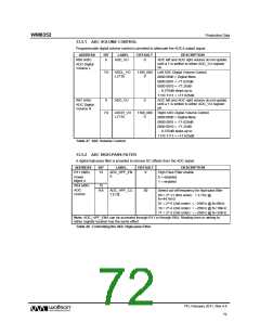
13.5.1 ADC VOLUME CONTROL
Programmable digital volume control is provided to attenuate the ADC’s output signal.
ADDRESS
BIT
LABEL
DEFAULT
DESCRIPTION
R66 (42h)
8
ADC_VU
0
ADC left and ADC right volume do not update
until a 1 is written to either ADC_VU register
bit.
ADC Digital
Volume L
7:0
ADCL_VO
L [7:0]
1100_000
0
Left ADC Digital Volume Control
0000 0000 = Digital Mute
0000 0001 = -71.625dB
0000 0010 = -71.25dB
... 0.375dB steps up to
1110 1111 = +17.625dB
R67 (43h)
8
ADC_VU
0
ADC left and ADC right volume do not update
until a 1 is written to either ADC_VU register
bit.
ADC Digital
Volume R
7:0
ADCR_VO
L [7:0]
1100_000
0
Right ADC Digital Volume Control
0000 0000 = Digital Mute
0000 0001 = -71.625dB
0000 0010 = -71.25dB
... 0.375dB steps up to
1110 1111 = +17.625dB
Table 27 ADC Volume Control
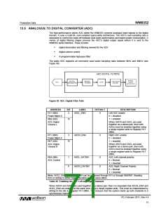
13.5.2 ADC HIGH-PASS FILTER
A digital high-pass filter is provided to remove DC offsets from the ADC signal.
ADDRESS
BIT
LABEL
DEFAULT
DESCRIPTION
High Pass Filter enable
R11 (0Bh)
13
ADC_HPF_EN
A
0
Power
Mgmt 4
0 = disabled
1 = enabled
R64 (40h)
15
ADC
Control
9:8
ADC_HPF_CU
T [1:0]
00
Select cut-off frequency for high-pass filter
00 = 2^-11 (first order) = 3.7Hz @
fs=44.1kHz
01 = 2^-5 (2nd order) = ~250Hz @ fs=8kHz
10 = 2^-4 (2nd order) = ~250Hz @ fs=16kHz
11 = 2^-3 (2nd order) = ~250Hz @ fs=32kHz
Note: ADC_HPF_ENA can be accessed through R11 or through R64. Reading from or writing to
either register location has the same effect.
Table 28 Controlling the ADC High-pass Filter
PD, February 2011, Rev 4.4
72
w

 WOLFSON [ WOLFSON MICROELECTRONICS PLC ]