Production Data
WM8352
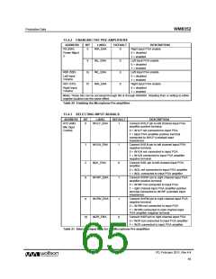
13.4.2 ENABLING THE PRE-AMPLIFIERS
ADDRESS
BIT
LABEL
DEFAULT
DESCRIPTION
Right input PGA enable
R9 (09h)
9
INR_ENA
0
Power Mgmt
2
0 = disabled
1 = enabled
8
INL_ENA
INL_ENA
INR_ENA
0
0
0
Left input PGA enable
0 = disabled
1 = enabled
R80 (50h)
15
15
Left input PGA enable
0 = disabled
Left Input
Volume
1 = enabled
R81 (51h)
Right input PGA enable
0 = disabled
Right Input
Volume
1 = enabled
Note: These bits can be accessed through R9 or through R80/R81. Reading from or writing to either
register location has the same effect.
Table 20 Enabling the Microphone Pre-amplifiers
13.4.3 SELECTING INPUT SIGNALS
ADDRESS
BIT
LABEL
DEFAULT
DESCRIPTION
R72 (48h)
0
IN1LP_ENA
1
Connect IN1LP pin to left channel input PGA
amplifier positive terminal.
Mic Input
Control
0 = IN1LP not connected to input PGA
1 = input PGA amplifier positive terminal
connected to IN1LP (constant input
impedance)
1
IN1LN_ENA
1
Connect IN1LN pin to left channel input PGA
negative terminal.
0 = IN1LN not connected to input PGA
1 = IN1LN connected to input PGA amplifier
negative terminal.
2
8
IN2L_ENA
0
1
Connect IN2L pin to left channel input PGA
amplifier
0 = IN2L not connected to input PGA amplifier
1 = IN2L connected to input PGA amplifier
IN1RP_ENA
Connect IN1RP pin to right channel input PGA
amplifier positive terminal.
0 = IN1RP not connected to input PGA
1 = right channel input PGA amplifier positive
terminal connected to IN1RP (constant input
impedance)
9
IN1RN_ENA
IN2R_ENA
1
0
Connect IN1RN pin to right channel input PGA
negative terminal.
0 = IN1RN not connected to input PGA
1 = IN1RN connected to right channel input
PGA amplifier negative terminal.
10
Connect IN2R pin to right channel input PGA
0 = IN2R not connected to input PGA amplifier
1 = IN2R connected to input PGA amplifier
Table 21 Selecting Input Pins for the Microphone Pre-amplifiers
PD, February 2011, Rev 4.4
65
w

 WOLFSON [ WOLFSON MICROELECTRONICS PLC ]