Production Data
WM8352
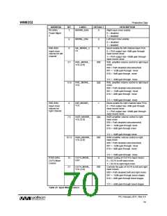
13.5 ANALOGUE TO DIGITAL CONVERTER (ADC)
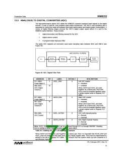
The high-performance stereo ADC within the WM8352 converts analogue input signals to the digital
domain. It uses a multi-bit, over-sampled sigma-delta architecture. The ADC’s over-sampling rate is
selectable to control the trade-off between best audio performance and lowest power consumption. A
variety of digital filtering stages process the ADC’s digital output signal before it is sent to the
WM8352 audio interface. These include:
.
.
.
digital decimation and filtering needed for the ADC
digital volume control
A programmable high-pass filter
The audio ADC supports all commonly used audio sampling rates between 8kHz and 48kHz (see
Figure 40).
Figure 40 ADC Digital Filter Path
ADDRESS
R11 (0Bh)
BIT
LABEL
DEFAULT
DESCRIPTION
Left ADC enable
2
ADCL_ENA
0
Power Mgmt 4
R66 (42h)
0 = disabled
1 = enabled
15
When ADCR and ADCL are used
together as a stereo pair, then both
ADCs must be enabled together using
a single register write to Register R11
(0Bh).
ADC Digital
Volume L
R11 (0Bh)
3
ADCR_ENA
0
Right ADC enable
0 = disabled
Power Mgmt 4
R67 (43h)
1 = enabled
15
When ADCR and ADCL are used
together as a stereo pair, then both
ADCs must be enabled together using
a single register write to Register R11
(0Bh).
ADC Digital
Volume R
R64 (40h)
1
0
ADCL_DATINV
ADCR_DATINV
0
0
ADC Left channel polarity:
0 = Normal
ADC Control
1 = Inverted
ADC Right Channel Polarity
0 = Normal
1 = Inverted
Note: ADCL_ENA and ADCR_ENA can be accessed through R11 or through R66/R67. Reading
from or writing to either register location has the same effect.
Table 26 Enabling the ADC Left and Right Channels
When ADCR and ADCL are used together as a stereo pair, then it is important that ADCR_ENA and
ADCL_ENA are enabled at the same time using a single register write. This must be implemented by
writing to the bits in Register R11 (0Bh). This ensures that the system starts up both channels in a
synchronous manner.
PD, February 2011, Rev 4.4
w
71

 WOLFSON [ WOLFSON MICROELECTRONICS PLC ]