WM8352
Production Data
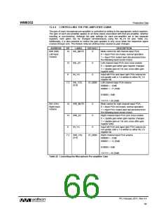
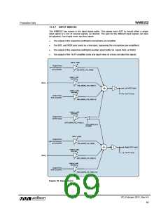
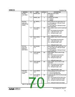
13.4.4 CONTROLLING THE PRE-AMPLIFIER GAINS
The gain of each microphone pre-amplifier is controlled by writing to the appropriate control registers.
The gain of each pre-amplifier applies to all three inputs associated with that pre-amplifier, whether
inverting or non-inverting. Although the gain settings for each pre-amplifier are in two separate
registers, both gains can be changed simultaneously using the IN_VU bit (see Table 22).
Additionally, it is also possible to control the gain updates to only occur when the respective signal
crosses through zero. This feature reduces clicking noise caused by gain changes.
ADDRESS
BIT
LABEL
DEFAULT
DESCRIPTION
R80 (50h)
14
INL_MUTE
0
Mute control for left channel input PGA:
0 = Input PGA not muted, normal operation
Left Input
Volume
1 = Input PGA muted (and disconnected from
the following input record mixer).
13
INL_ZC
IN_VU
0
Left channel input PGA zero cross enable:
0 = Update gain when gain register changes
1 = Update gain on 1st zero cross after gain
register write.
8
0
Input left PGA and input right PGA volume do
not update until a 1 is written to either IN_VU
register bit.
7:2
INL_VOL
[5:0]
01_0000
Left channel input PGA volume
000000 = -12dB
000001 = -11.25dB
.
010000 = 0dB
.
111111 = 35.25dB
R81 (51h)
14
13
INR_MUTE
INR_ZC
IN_VU
0
0
Mute control for right channel input PGA:
0 = Input PGA not muted, normal operation
Right Input
Volume
1 = Input PGA muted (and disconnected from
the following input record mixer).
Right channel input PGA zero cross enable:
0 = Update gain when gain register changes
1 = Update gain on 1st zero cross after gain
register write.
8
0
Input left PGA and input right PGA volume do
not update until a 1 is written to either IN_VU
register bit.
7:2
INR_VOL
[5:0]
01_0000
Right channel input PGA volume
000000 = -12dB
000001 = -11.25dB
.
010000 = 0dB
.
111111 = 35.25dB
Table 22 Controlling the Microphone Pre-amplifier Gain
PD, February 2011, Rev 4.4
66
w

 WOLFSON [ WOLFSON MICROELECTRONICS PLC ]