WM8352
Production Data
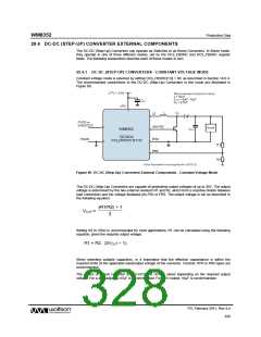
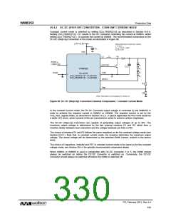
29.4.2 DC-DC (STEP-UP) CONVERTERS - CONSTANT CURRENT MODE
Constant current mode is selected by setting DCn_FBSRC[1:0] as described in Section 14.6.4.
Setting DCn_FBSRC[1:0] = 01 results in the DC Converter controlling the current at ISINKA, whilst
setting DCn_FBSRC[1:0] = 10 controls the current at ISINKB. The recommended connections to the
DC-DC (Step-Up) Converters in this mode are illustrated in Figure 90.
Figure 90 DC-DC (Step-Up) Converters External Components - Constant Current Mode
In the constant current mode, the DC-DC Converter output voltage is controlled by the WM8352 in
order to achieve the required current in ISINKA or ISINKB. The required current is set by the
CSn_ISEL register fields, as described in Section 16.2.2. A typical application for this mode would be
a white LED driver, where several LEDs are connected in series to achieve uniform brightness.
The DC-DC (Step-Up) Converters are capable of generating output voltages of up to 30V. The
maximum output voltage is determined by the two external resistors R1 and R2, which form a
resistive divider between load connection and the voltage feedback pin FB2 or FB5.
The choice of resistors R1 and R2 follows the same equations as for the constant voltage mode (see
Section 29.4.1). Note that, in constant current mode, the resistors determine the maximum output
voltage. The actual voltage will be determined by the selected ISINK current, subject to the device
limits.
The choice of Capacitors, Inductor and FET in constant current mode is the same as for the constant
voltage mode; see Section 29.4.4 for specific recommended component details.
When ISINKA or ISINKB is used in conjunction with DC-DC Converter 2 or 5, the ISINK should
always be switched on before the DC-DC Converter is switched on. Conversely, the DC-DC
Converter should always be switched off before the ISINK is switched off.
PD, February 2011, Rev 4.4
330
w

 WOLFSON [ WOLFSON MICROELECTRONICS PLC ]