WM8352
Production Data
29.2 VOLTAGE REFERENCE (VREF) COMPONENTS
A decoupling capacitor is required between CREF and REFGND; a 2.2uF X5R capacitor is
recommended.
A
reference resistor is required between RREF and REFGND; a 100kΩ (1%) resistor is
recommended.
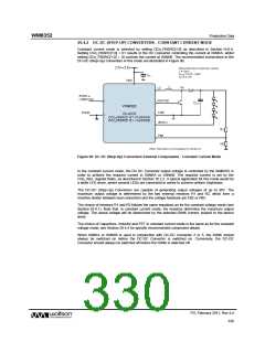
29.3 DC-DC (STEP-DOWN) CONVERTER EXTERNAL COMPONENTS
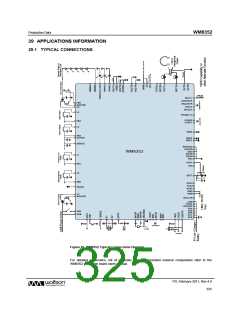
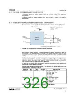
The recommended connections to the DC-DC (Step-Down) Converters are illustrated in Figure 88.
Figure 88 DC-DC (Step-Down) Converters External Components
When selecting suitable capacitors, is it imperative that the effective capacitance is within the
required limits at the applicable input/output voltage of the converter. It should be noted that some
components’ capacitance changes significantly depending on the DC voltage applied. Ceramic X7R
or X5R types are recommended.
The choice of output capacitor for DC-DC1 and DC-DC6 varies depending on the required transient
response. A value of 30μF is recommended in the first instance. Larger values (up to 100μF) may be
required for optimum performance under large load transient conditions. Smaller values (down to
10μF) may be sufficient for a steady load in some applications.
For layout and size reasons, users may choose to implement large values of output capacitance by
connecting two or more capacitors in parallel.
To ensure stable operation, the register fields DC1_CAP and DC6_CAP must be set according to the
output capacitance, as detailed in Table 156.
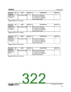
ADDRESS
BIT
LABEL
DEFAULT
DESCRIPTION
DC-DC1 Output Capacitor
00 = 10uF, 30uF, 45uF
01 = 60uF, 85uF
R180 (B4h)
15:14
DC1_CAP
00
10 = Not used
11 = 100uF
R195 (C3h)
15:14
DC6_CAP
00
DC-DC6 Output Capacitor
00 = 10uF, 30uF, 45uF
01 = 60uF, 85uF
10 = Not used
11 = 100uF
Table 156 Register Control for DC-DC1 and DC-DC6 Output Capacitor
PD, February 2011, Rev 4.4
326
w

 WOLFSON [ WOLFSON MICROELECTRONICS PLC ]