Production Data
WM8352
REGISTER
ADDRESS
BIT
LABEL
DEFAULT
DESCRIPTION
REFER TO
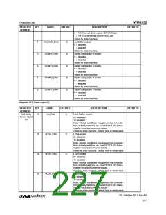
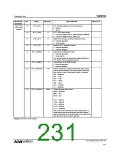
R23 (17h)
RTC Time
Control
15
RTC_BCD
0
RTC Coding (applies to all time registers)
0 = Binary
1 = BCD
14
11
10
9
RTC_12HR
RTC_SET
0
0
0
1
RTC 12/24 hours mode
1 = 12 hours (MSB of RTC_HRS indicates AM/PM)
0 = 24 hours (MSB of RTC_HRS is 0)
Stops RTC seconds counter (instruction only)
0 = normal operation
1 = stop counter
RTC_STS
Status of RTC seconds counter
0 = normal operation
1 = counter stopped
RTC_ALMSET
Stops alarms (instruction only)
0 = normal operation
1 = stop alarms
It is recommended to stop alarms when setting the
RTC alarm. This avoids false alarms.
8
RTC_ALMSTS
RTC_PINT[2:0]
1
Actual status of ALARM circuitry
0 = normal operation
1 = alarms stopped
6:4
010
Selects frequency of periodic interrupt output pulse
(32kHz period duration) as shown below. When set
time status is high, the periodic output is disabled.
000 = disabled
001 = 1 sec
010 = 1 min
011 = 1 hour
100 = 1 day
101 = 1 month
11x = disabled
Divided Square wave select.
0000 = disabled
0001 = 1Hz
3:0
RTC_DSW[3:0]
0000
0010 = 2Hz
…
1011 = 1024Hz
1100 = 2048Hz
1101 = 4096Hz
1110 = 8192Hz
1111 = 16384Hz
Note: due to trim settings for crystal intolerances a
single square wave period during seconds rollover
may be decrease its on time period or increase its off
time period by up to 8 32kHz periods.
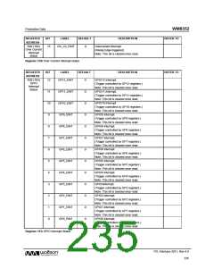
Register 17h RTC Time Control
PD, February 2011, Rev 4.4
231
w

 WOLFSON [ WOLFSON MICROELECTRONICS PLC ]