Production Data
WM8352
ADDRESS
BIT
LABEL
DEFAULT
DESCRIPTION
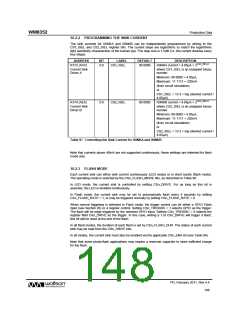
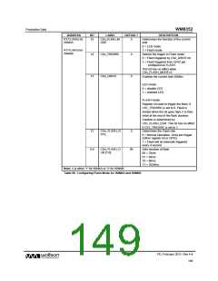
R173 (ADh) for
ISINKA
15
CSn_FLASH_M
ODE
0
Determines the function of the current
sink
0 = LED mode
R175 (AFh) for
ISINKB
1 = Flash mode
14
13
CSn_TRIGSRC
CSn_DRIVE
0
0
Selects the trigger in Flash mode.
0 = Flash triggered by CSn_DRIVE bit
1 = Flash triggered from GPIO pin
configured as FLASH
This bit has no effect when
CSn_FLASH_MODE=0
Enables the current sink ISINKn
LED mode-
0 = disable LED
1 = enabled LED
FLASH mode-
Register bit used to trigger the flash, if
CS1_TRIGSRC is set to 0. Flash is
started when the bit goes high, it is then
reset at the end of the flash duration.
Duration is determined by
CS1_FLASH_DUR. This bit has no effect
if CS1_TRIGSRC is set to 1.
12
CSn_FLASH_R
ATE
0
Determines the Flash rate
0 = Normal Operation. Once per trigger
(Either register bit or GPIO)
1 = Flash will be internally triggered
every 4 second
9:8
CSn_FLASH_D
UR [1:0]
00
Sets duration of flash
00 = 32ms
01 = 64ms
10 = 96ms
11 = 1024ms
Note: n is either ‘1’ for ISINKA or ‘2’ for ISINKB
Table 98 Configuring Flash Mode for ISINKA and ISINKB
PD, February 2011, Rev 4.4
149
w

 WOLFSON [ WOLFSON MICROELECTRONICS PLC ]