Production Data
WM8352
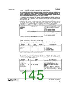
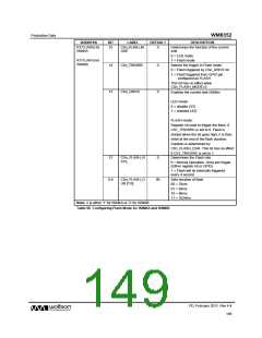
15.2.2 CURRENT LIMIT SWITCH BULK DETECTION CONTROL
The Current Limit Switch can be connected to voltages which may be higher than the device LINE
voltage. To support this capability, the switch is powered from the highest available voltage; this
requires a bulk detection circuit in order to select the highest available voltage. The bulk detection
circuit is always enabled whenever the Current Limit Switch is enabled.
It is possible to control whether the bulk detection circuit is enabled or not when the Current Limit
Switch is disabled. This is controlled in Active mode by the LS_PROT bit, and in Hibernate mode by
the LS_HIB_PROT bit.
Disabling the Bulk Detection circuit will reduce power consumption. It is important to note, however,
that the Bulk Detection circuit should always be enabled if voltages greater than LINE could be
present on IP or OP. This applies regardless of whether the Current Switch is open or closed.
ADDRESS
BIT
LABEL
DEFAULT
DESCRIPTION
R199 (C7h)
1
LS_HIB_PRO
T
1
Controls the bulk detection circuit when
Limit Switch is disabled in Hibernate
mode.
Limit switch
control
0 = bulk detection disabled
1 = bulk detection enabled
0
LS_PROT
1
Controls the bulk detection circuit when
Limit Switch is disabled in Active mode.
0 = bulk detection disabled
1 = bulk detection enabled
Table 92 Current Limit Switch Bulk Detection Control
15.2.3 INTERRUPTS AND FAULT PROTECTION
The response to an over-current condition is selectable. To prevent false alarms during short current
surges, faults are only signalled if the fault condition persists.
ADDRESS
BIT
LABEL
DEFAULT
DESCRIPTION
Current limit detection behaviour
00 = ignore
R199 (C7h)
15:14
LS_ERRACT
[1:0]
00
Limit switch
control
01 = disable switch
10 = shut down system
11 = shut down system
Table 93 Fault Response for the Current Limit Switch
The limit switch has its own first-level interrupt, OC_INT (see Section 24). This contains a single
second-level interrupt, OC_LS_EINT, indicating an over-current condition. OC_LS_EINT can be
masked by setting the IM_OC_LS_EINT bit.
ADDRESS
BIT
LABEL
OC_LS_EINT
DESCRIPTION
Limit Switch Over-current interrupt.
(Rising Edge triggered)
R29 (1Dh)
15
Over Current
Interrupt Status
Note: This bit is cleared once read.
R37 (25h)
15
IM_OC_LS_EINT
Mask bit for Limit switch over-current
interrupt
Over Current
Interrupt Mask
When set to 1, IM_OC_LS_EINT masks
OC_LS_EINT in R29 and does not trigger
an OC_INT interrupt when OC_LS_EINT is
set).
Table 94 Current Limit Switch Interrupts
PD, February 2011, Rev 4.4
145
w

 WOLFSON [ WOLFSON MICROELECTRONICS PLC ]