Production Data
WM8352
16 CURRENT SINKS (LED DRIVERS)
16.1 GENERAL DESCRIPTION
The WM8352 includes five pins for driving different types of LEDs.
The pins ISINKA and ISINKB provide programmable constant-current sinks designed to drive strings
of serially connected LEDs, including white LEDs used in display backlights or in camera flash
applications. Using ISINKA and ISINKB in conjunction with DC-DC Converters 2 or 5 provides a
particularly power-efficient way to drive such LED strings. The ground connection associated with
these two Current Sinks is the SINKGND pin.
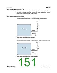
ISINKC, ISINKD and ISINKE are regular open-drain outputs. They are alternate functions of the
GPIO10, GPIO11 and GPIO12 pins respectively. These GPIOs are provided on the LINE power
domain; the associated ground connection is the GND pin.
16.2 CONSTANT-CURRENT SINKS
ISINKA and ISINKB are dedicated LED driver pins equipped with programmable constant current
sinks. They are designed to drive strings of serially connected white LEDs such as those used in
display backlights or photo-flash applications. Powering LEDs in this way is particularly power
efficient because no series resistor is required. DC-DC converters 2 or 5, operating as a current-
controlled voltage source, are ideal power sources for LED strings. These converters can generate
voltages higher than BATT or LINE, which can overcome the combined forward voltages of long LED
strings (e.g. a string of 7 white LEDs with a forward voltage of 4V requires at least 28V).
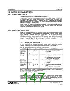
16.2.1 ENABLING THE SINK CURRENT
In Active mode, ISINKA and ISINKB can be enabled in software using the register fields defined in
Table 96. If required, the Current Sink functions may also be controlled by the Hibernate bit.
Note that these control bits do not exist for ISINKC, ISINKD or ISINKE.
ADDRESS
BIT
LABEL
DEFAULT
DESCRIPTION
Current Sink 1 enable (ISINKA pin)
0 = disabled
R14 (0Eh)
Power mgmt
(7)
0
CS1_ENA
0
1 = enabled
R172 (ACh)
15
12
Current Sink
Driver A
CS1_HIB_MO
DE
0
Current Sink 1 behaviour in Hibernate
mode
0 = disable current sink in Hibernate
1 = leave current sink as in Active
Current Sink 2 enable (ISINKB pin)
0 = disabled
R14 (0Eh)
Power mgmt
(7)
1
CS2_ENA
0
0
1 = enabled
R174 (AEh)
15
12
Current Sink
Driver B
CS2_HIB_MO
DE
Current Sink 2 behaviour in Hibernate
mode
0 = disable current sink in Hibernate
1 = leave current sink as in Active
Note: CS1_ENA and CS2_ENA can be accessed through R14 or through R172/R174. Reading from
or writing to either register location has the same effect.
Table 96 Enabling ISINKA and ISINKB
When ISINKA or ISINKB is used in conjunction with DC-DC Converter 2 or 5, the ISINK should
always be switched on before the DC-DC Converter is switched on. Conversely, the DC-DC
Converter should always be switched off before the ISINK is switched off. If high voltages are used,
additional external components may also be needed to protect the WM8352.
PD, February 2011, Rev 4.4
147
w

 WOLFSON [ WOLFSON MICROELECTRONICS PLC ]