WM8352
Production Data
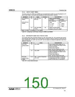
16.2.4 ON/OFF RAMP TIMING
The sink currents for ISINKA and ISINKB can be programmed to switch on and off gradually in LED
and in Flash modes. The current ramp durations are set as described in Table 99.
ADDRESS
BIT
LABEL
DEFAULT
DESCRIPTION
R173 (ADh) for
ISINKA
5:4
CSn_OFF_RA
MP [1:0]
00
Switch-off ramp duration
LED Mode
Flash Mode
00 = instant (no
ramp)
00 = instant (no
ramp)
R175 (AFh) for
ISINKB
01 = 0.25s
10 = 0.5s
11 = 1s
01 = 1.95ms
10 = 3.91ms
11 = 7.8ms
1:0
CSn_ON_RAM
00
Switch-on ramp duration
P [1:0]
Similar to CSn_OFF_RAMP
Note: n is either ‘1’ for ISINKA or ‘2’ for ISINKB
Table 99 Configuring On/Off Ramp Timing for ISINKA and ISINKB
16.2.5 INTERRUPTS AND FAULT PROTECTION
The Current Sinks have a first-level interrupt, CS_INT (see Section 24). This comprises two second-
level interrupts which indicate if the Current Sinks are unable to sink the amount of current that has
been programmed. CS1_EINT and CS2_EINT can be masked by setting the applicable mask bit as
defined in Table 100.
ADDRESS
BIT
LABEL
DESCRIPTION
R26 (1Ah)
13
CS1_EINT
Flag to indicate drain voltage can no
longer be regulated and output current
may be out of spec.
Interrupt Status
2
(Rising Edge triggered)
Note: This bit is cleared once read.
12
CS2_EINT
Flag to indicate drain voltage can no
longer be regulated and output current
may be out of spec.
(Rising Edge triggered)
Note: This bit is cleared once read.
R34 (22h)
13:12
“IM_” + name of respective
bit in R26
Each bit in R34 enables or masks the
corresponding bit in R26. The default
value for these bits is 0 (unmasked).
Interrupt Status
2 Mask
Table 100 Current Sink Interrupts
PD, February 2011, Rev 4.4
150
w

 WOLFSON [ WOLFSON MICROELECTRONICS PLC ]