WM8352
Production Data
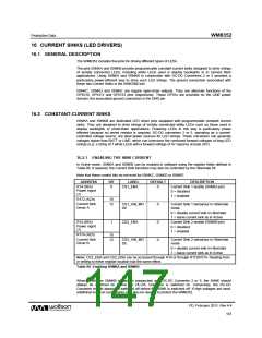
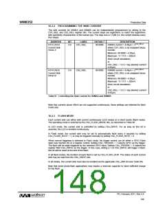
16.2.2 PROGRAMMING THE SINK CURRENT
The sink currents for ISINKA and ISINKB can be independently programmed by writing to the
CS1_ISEL and CS2_ISEL register bits. The current steps are logarithmic to match the logarithmic
light sensitivity characteristic of the human eye. The step size is 1.5dB (i.e. the current doubles every
four steps).
ADDRESS
BIT
LABEL
DEFAULT
DESCRIPTION
ISINKA current = 4.05μA × 2CSn_ISEL/4
R172 (ACh)
5:0
CS1_ISEL
00 0000
Current Sink
Driver A
where CS1_ISEL is an unsigned binary
number
Minimum: 00 0000 = 4.05μA,
Maximum: 11 1111 = 220mA
(from circuit simulation)
or
CS1_ISEL = 13.3 × log (desired current /
4.05μA)
R174 (AEh)
5:0
CS2_ISEL
00 0000
ISINKB current = 4.05μA × 2CSn_ISEL/4
Current Sink
Driver B
where CS2_ISEL is an unsigned binary
number
Minimum: 00 0000 = 4.05μA,
Maximum: 11 1111 = 220mA
(from circuit simulation)
or
CS2_ISEL = 13.3 × log (desired current /
4.05μA)
Table 97 Controlling the Sink Current for ISINKA and ISINKB
Note that currents above 40mA are not supported continuously; these settings are intended for flash
mode only.
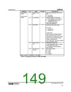
16.2.3 FLASH MODE
Each current sink can either sink current continuously (LED mode) or in short bursts (flash mode).
The operating mode is selected by the CSn_FLASH_MODE bits, as described in Table 98.
In LED mode, the current sink is controlled by setting CSn_DRIVE. For as long as this bit is
asserted, the LED is enabled continuously.
In Flash mode, the current sink may be set to automatically flash every 4 seconds by setting
CSn_FLASH_RATE = 1, or may be triggered normally by setting CSn_FLASH_RATE = 0.
When normal triggering is selected in Flash mode, the trigger control can be either a GPIO Flash
input (see Section 20) or a register control. Setting CSn_TRIGSRC = 1 selects GPIO as the trigger.
The flash will be edge triggered by the selected GPIO input. Setting CSn_TRIGSRC = 0 selects the
register field CSn_DRIVE as the trigger. In this case, writing a 1 to CSn_DRIVE will trigger a flash;
this bit will be reset at the end of the flash.
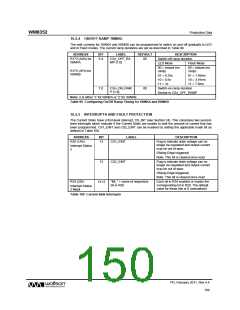
In all flash modes, the duration of each flash is set by CSn_FLASH_DUR. The status of each current
sink may be read from the CSn_DRIVE bits.
In all modes, the current sink must also be enabled via the applicable CSn_ENA bit (see Table 96).
Note that some photo-flash applications may require a reservoir capacitor to store sufficient charge
for the flash.
PD, February 2011, Rev 4.4
148
w

 WOLFSON [ WOLFSON MICROELECTRONICS PLC ]