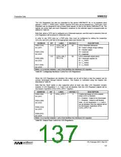
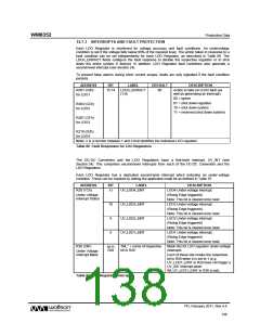
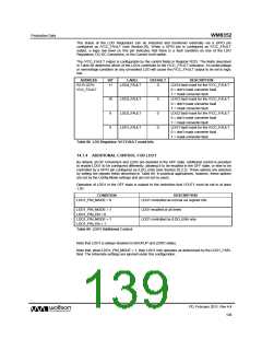
Production Data
WM8352
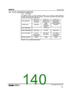
14.8.2 DC-DC STEP DOWN CONVERTERS
DC-DC Converters 1, 3, 4 and 6 are versatile step-down, pulse-width-modulated (PWM) DC-DC
converters designed to deliver high power efficiency across full load conditions. The converters offer
Active and Standby/Hysteretic operating modes in order to maximise efficiency for different loads. A
low-power LDO sleep mode is also available to further reduce quiescent current at very lightly loaded
conditions. The DC-DC Converters maintain output voltage regulation during the switch-over between
operating modes.
The step-down regulators are designed with a fixed frequency current mode architecture. The current
feedback loop is through the PMOS current path and is amplified and summed with an internal slope
compensation network. The voltage feedback loop is through an internal feedback divider. The ON
time is determined by comparing the summed current feedback and the output of the switcher error
amplifier. The period is set by the internal RC oscillator, which provides a 2.0MHz clock.
A supply pin (PVDD) provides the core supply for DC-DC Converters 3 and 6. Another supply pin
(LINEDCDC) provides the core supply for DC-DC Converters 1 and 4. The input voltage connection
to DC-DC Converters 1, 3, 4 and 6 is provided on PV1, PV3, PV4 and PV6 respectively. These input
voltages may be provided from the LINE voltage.
The connections to DC-DC Converter 1 are illustrated in Figure 69. The equivalent circuit applies to
DC-DC Converters 3, 4 and 6 also.
Figure 69 Step-Down DC-DC Converter Connections
The external components at the converter output are required by the DC-DC Converter integral loop
compensation circuit. Note that the recommended output capacitor Cout varies according to the
required transient response on DC-DC1 and DC-DC6. A single recommended value is provided for
Cout on DC-DC3 and DC-DC4.
See Section 29.3 for details of the recommended external components.
PD, February 2011, Rev 4.4
141
w

 WOLFSON [ WOLFSON MICROELECTRONICS PLC ]