WM8352
Production Data
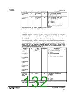
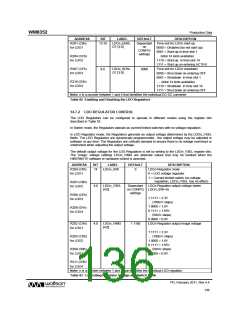
ADDRESS
R201 (C9h)
for LDO1
BIT
LABEL
DEFAULT
DESCRIPTION
13:10
LDOn_ENSL
OT [3:0]
Dependant Time slot for LDOn start-up
on
CONFIG
settings
0000 = Disabled (do not start up)
0001 = Start-up in time slot 1
… (total 14 slots available)
R204 (CCh)
for LDO2
1110 = Start-up in time slot 14
1111 = Start up on entering ACTIVE
Time slot for LDOn shutdown.
0000 = Shut down on entering OFF
0001 = Shutdown in time slot 1
…. (total 14 slots available)
R207 (CFh)
for LDO3
9:6
LDOn_SDSL
OT [3:0]
0000
R210 (D2h)
for LDO4
1110 = Shutdown in time slot 14
1111 = Shut down on entering OFF
Note: n is a number between 1 and 4 that identifies the individual DC-DC converter
Table 82 Enabling and Disabling the LDO Regulators
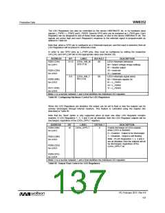
14.7.2 LDO REGULATOR CONTROL
The LDO Regulators can be configured to operate in different modes using the register bits
described in Table 83.
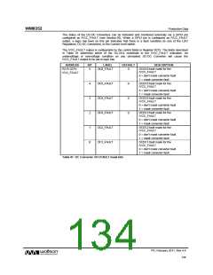
In Switch mode, the Regulators operate as current-limited switches with no voltage regulation.
In LDO Regulator mode, the Regulators generate an output voltage determined by the LDOn_VSEL
fields. The LDO Regulators are dynamically programmable - the output voltage may be adjusted in
software at any time. The Regulators are critically damped to ensure there is no voltage overshoot or
undershoot when adjusting the output voltage.
The default output voltage for the LDO Regulators is set by writing to the LDOn_VSEL register bits.
The ‘image’ voltage settings LDOn_VIMG are alternate values that may be invoked when the
HIBERNATE software or hardware control is asserted.
ADDRESS
R200 (C8h)
for LDO1
BIT
LABEL
DEFAULT
DESCRIPTION
LDOn Regulator mode
14
LDOn_SWI
0
0 = LDO voltage regulator
1 = Current-limited switch (no voltage
regulation, LDOn_VSEL has no effect)
R203 (CBh)
for LDO2
4:0
LDOn_VSEL
[4:0]
Dependant
LDOn Regulator output voltage (when
on CONFIG LDOn_SWI=0)
settings
R206 (CEh)
for LDO3
1 1111 = 3.3V
… (100mV steps)
1 0000 = 1.8V
0 1111 = 1.65V
… (50mV steps)
0 0000 = 0.9V
R209 (D1h)
for LDO4
R202 (CAh)
for LDO1
4:0
LDOn_VIMG
[4:0]
1 1100
LDOn Regulator output image voltage
1 1111 = 3.3V
… (100mV steps)
1 0000 = 1.8V
0 1111 = 1.65V
… (50mV steps)
0 0000 = 0.9V
R205 (CDh)
for LDO2
R208 (D0h)
for LDO3
R211 (D3h)
for LDO4
Note: n is a number between 1 and 4 that identifies the individual LDO regulator
Table 83 Controlling Regulator Voltage and Switch Mode
PD, February 2011, Rev 4.4
136
w

 WOLFSON [ WOLFSON MICROELECTRONICS PLC ]