Production Data
WM8352
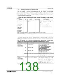
The status of the LDO Regulators can be indicated and monitored externally via a GPIO pin
configured as /VCC_FAULT (see Section 20). When a GPIO pin is configured as /VCC_FAULT
output, a logic low level on this pin indicates that there is a fault condition on one of the LDO
Regulators, DC-DC Converters, or the Current Limit switch.
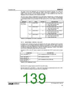
The /VCC_FAULT output is configurable by the control fields in Register R215. The fields described
in Table 88 determine which of the LDOs contribute to the /VCC_FAULT indication. An undervoltage
or overvoltage condition on any unmasked LDO will cause the /VCC_FAULT output to be set to logic
low.
ADDRESS
R215 (D7h)
VCC_FAULT
BIT
LABEL
DEFAULT
DESCRIPTION
11
LDO4_FAULT
0
LDO4 fault mask for the /VCC_FAULT
0 = don't mask converter fault
1 = mask converter fault
10
9
LDO3_FAULT
LDO2_FAULT
LDO1_FAULT
0
0
0
LDO3 fault mask for the /VCC_FAULT
0 = don't mask converter fault
1 = mask converter fault
LDO2 fault mask for the /VCC_FAULT
0 = don't mask converter fault
1 = mask converter fault
8
LDO1 fault mask for the /VCC_FAULT
0 = don't mask converter fault
1 = mask converter fault
Table 88 LDO Regulator /VCCFAULT mask bits
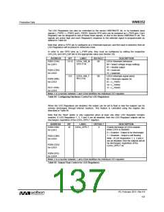
14.7.4 ADDITIONAL CONTROL FOR LDO1
By default, all DC Converters and LDOs are disabled in the OFF state. Additional control is provided
to enable LDO1 to be configured differently, allowing it to be enabled in the OFF state, or else to be
controlled by a GPIO pin configured as /LDO_ENA (see Section 20.2.2). These options are selected
by setting the register fields described in Table 89. In practical applications, however, these options
are set by the Config Mode settings and are not set by users.
Operation of LDO1 in the OFF state is subject to the restriction that VOUT1 must be set to at least
1.8V.
CONDITION
LDO1_PIN_MODE = 0
DESCRIPTION
LDO1 controlled as normal via register bits
LDO1_PIN_MODE = 1
LDO1_PIN_EN = 0
LDO1_PIN_MODE = 1
LDO1_PIN_EN = 1
LDO1 enabled at all times
LDO1 controlled by /LDO_ENA only
Table 89 LDO1 Additional Control
Note that LDO1 is always disabled in BACKUP and ZERO states.
Note that, when LDO1_PIN_MODE = 1, then LDO1 only operates as determined by the LDO1_VSEL
field. The Hibernate settings are ignored under this configuration.
PD, February 2011, Rev 4.4
139
w

 WOLFSON [ WOLFSON MICROELECTRONICS PLC ]