WM8352
Production Data
14.7.3 INTERRUPTS AND FAULT PROTECTION
Each LDO Regulator is monitored for voltage accuracy and fault conditions. An undervoltage
condition is set if the voltage falls below 95% of the required level. The action taken in response to a
fault condition can be set independently for each LDO Regulator, as described in Table 86. The
LDOn_ERRACT fields configure the fault response to disable the respective regulator or to shut
down the entire system if desired. In addition, LDO Regulator fault conditions also generate a
second-level interrupt (see Section 24).
To prevent false alarms during short current surges, faults are only signalled if the fault condition
persists.
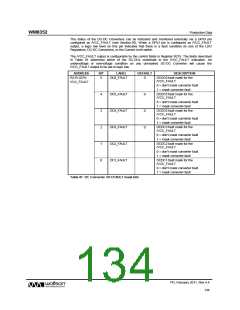
ADDRESS
R201 (C9h)
for LDO1
BIT
LABEL
DEFAULT
DESCRIPTION
15:14
LDOn_ERRACT
00
Action to take on LDOn fault (as
well as generating an interrupt):
[1:0]
00 = ignore
01 = shut down regulator
10 = shut down system
11 = reserved (shut down system)
R204 (CCh)
for LDO2
R207 (CFh)
for LDO3
R210 (D2h)
for LDO4
Note: n is a number between 1 and 4 that identifies the individual LDO regulator
Table 86 Fault Responses for LDO Regulators
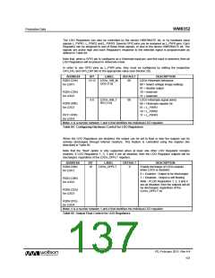
The DC-DC Converters and the LDO Regulators have
a first-level interrupt, UV_INT (see
Section 24). This comprises second-level interrupts from each of the DC-DC Converters and the
LDO Regulators.
Each LDO Regulator has a dedicated second-level interrupt which indicates an under-voltage
condition. These can be masked by setting the applicable mask bit as defined in Table 87.
ADDRESS
R28 (1Ch)
BIT
LABEL
DESCRIPTION
LDO4 Under-voltage interrupt.
(Rising Edge triggered)
11
UV_LDO4_EINT
Under Voltage
Interrupt Status
Note: This bit is cleared once read.
LDO3 Under-voltage interrupt.
(Rising Edge triggered)
10
9
UV_LDO3_EINT
UV_LDO2_EINT
UV_LDO1_EINT
Note: This bit is cleared once read.
LDO2 Under-voltage interrupt.
(Rising Edge triggered)
Note: This bit is cleared once read.
LDO1 Under-voltage interrupt.
(Rising Edge triggered)
8
Note: This bit is cleared once read.
R36 (24h)
as in
R28
“IM_” + name of respective
bit in R28
Mask bits for LDO regulator under-voltage
interrupts
Under Voltage
Interrupt Mask
Each of these bits masks the respective
bit in R28 when it is set to 1 (e.g.
UV_LDO1_EINT in R28 does not trigger a
UV_INT interrupt when
IM_UV_LDO1_EINT in R36 is set).
Table 87 LDO Regulator Interrupts
PD, February 2011, Rev 4.4
138
w

 WOLFSON [ WOLFSON MICROELECTRONICS PLC ]