W9825G6KH
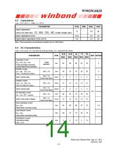
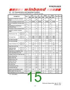
9.5 AC Characteristics and Operating Condition
(VDD = 3.3V ± 0.3V, TA = 0 to 70°C for -5/-6/-6L/-75/75L, TA = -40 to 85°C for -5I/-6I)
-5/-5I
-6
-6I/-6L
MIN.
-75/75L
PARAMETER
SYM.
UNIT NOTES
MIN. MAX. MIN. MAX.
MAX. MIN. MAX.
Ref/Active to Ref/Active Command
Period
tRC
tRAS
tRCD
55
60
60
42
18
65
Active to precharge Command Period
40 100000
15
42 100000
15
100000
45 100000 nS
20
Active to Read/Write Command Delay
Time
Read/Write(a) to Read/Write(b)
Command Period
tCCD
tRP
1
15
2
1
15
2
1
18
2
1
20
2
tCK
nS
tCK
Precharge to Active Command Period
Active(a) to Active(b) Command
Period
tRRD
CL* = 2
Write Recovery Time
CL* = 3
2
2
2
2
2
2
2
tWR
tCK
2
CL* = 2
CLK Cycle Time
7.5
5
1000
1000
7.5
6
1000
1000
7.5
6
1000
1000
10
7.5
2.5
2.5
1000
1000
tCK
CL* = 3
CLK High Level width
CLK Low Level width
tCH
tCL
2
2
2
8
8
2
2
2
CL* = 2
Access Time from CLK
CL* = 3
6
6
5
6
5
6
tAC
tOH
tHZ
9
9
7
9
4.5
5.4
Output Data Hold Time
3
3
3
3
CL* = 2
6
6
5
6
5
6
Output Data High
Impedance Time
CL* = 3
4.5
5.4
Output Data Low Impedance Time
Power Down Mode Entry Time
Transition Time of CLK (Rise and Fall)
Data-in Set-up Time
tLZ
tSB
0
0
0
0
0
0
0
0
5
1
6
1
6
1
7.5
1
nS
tT
tDS
1.5
1.0
1.5
1.0
1.5
1.0
1.5
1.0
1.5
0.8
1.5
0.8
1.5
0.8
1.5
0.8
1.5
0.8
1.5
0.8
1.5
0.8
1.5
0.8
1.5
1.0
1.5
1.0
1.5
1.0
1.5
1.0
8
8
8
8
8
8
8
8
Data-in Hold Time
tDH
Address Set-up Time
tAS
Address Hold Time
tAH
CKE Set-up Time
tCKS
tCKH
tCMS
tCMH
tREF
tRSC
tXSR
CKE Hold Time
Command Set-up Time
Command Hold Time
Refresh Time (8K Refresh Cycles)
Mode register Set Cycle Time
Exit self refresh to ACTIVE command
64
64
64
64
mS
tCK
2
2
2
2
70
72
72
75
nS
* CL = CAS Latency
Publication Release Date: Sep. 01, 2014
Revision: A02
- 15 -

 WINBOND [ WINBOND ]