Preliminary W91030B
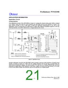
Application Information, continued
22nF
+5V
+5V
+5V
Tip/A
430K
34K
+5V
+5V
0.1uF
W91030B
INP
VDD
ALGRC
ALGR
ALGO
INTN
INN
22nF
464K
Ring/B
430K
34K
GCFB
VREF
CAP
R1
R2
60K4
53K6
0.33uF
(This net must as short as
0.1uF
RNGDI
RNGRC
RNGON
MODE
OSCI
OSCO
VSS
FCDN
FDRN
DATA
DCLK
FSKE
+5V
0.1uF
+5V
200K
150K
SLEEP/
RESET
TEST
12K
+
0.01uF
0.22uF
Must reset by
microcontroller
or by RC pulse.
Vz
-
470K
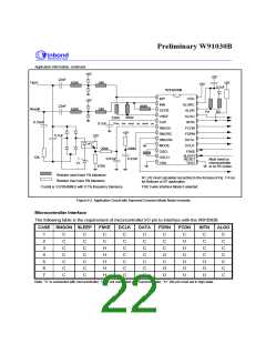
Resistor must have 1% tolerance.
Resistor may have 5% tolerance.
R1, R2 must calculated according to the formula of Fig. 7-6 (a)
for Bellcore or BT application.
Crystal is 3.579545MHz with 0.1% frequency tolerance.
FSK 3-wire interface Mode 0 selected.
Figure 9-2. Application Circuit with Improved Common Mode Noise Immunity
Microcontroller Interface
The following table is the requirement of micorcontroller I/O pin to interface with the W91030B:
CASE RNGON SLEEP
FSKE
DCLK
DATA
FDRN
FCDN
C
INTN
C
ALGO
1
2
3
4
5
6
7
C
C
C
C
C
C
C
C
C
C
C
C
C
C
C
C
H
H
H
H
H
C
C
C
C
C
C
O
C
C
C
C
C
C
C
C
C
C
O
C
O
O
C
C
C
C
C
C
C
O
C
O
C
O
C
O
O
O
O
O
O
Note: "C" is connected with microcontroller, "O" is not connected with microcontroller, "H": this pin must set in high state.
- 22 -

 WINBOND [ WINBOND ]