W83195WG-382/W83195CG-382
STEPLESS FOR ATI K8 CLOCK GENERATOR
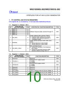
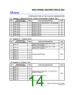
7. I2C CONTROL AND STATUS REGISTERS
(The register No. is increased by 1 if use byte data read/write protocol)
7.1 Register 0: ( Default : 00h )
AFFECTED PIN/
FUNCTION NAME(S)
BIT
PWD
AFFECTED PIN / FUNCTION DESCRIPTION
TYPE
7
SSEL<4>
0
6
5
4
3
SSEL<3>
SSEL<2>
SSEL<1>
SSEL<0>
0
0
0
0
Software frequency table selection through I2C
R/W
Enable software table selection FS[4:0].
0 = Hardware table setting (Jump mode).
1 = Software table setting through Bit7~3 .
(Jumpless mode)
Enable spread spectrum mode under clock
output.
2
EN_SSEL
0
R/W
R/W
1
SPSPEN
0
0 = Spread Spectrum mode disable
1 = Spread Spectrum mode enable
After watchdog timeout
0 = Reload the hardware FS [4:0] latched
pins setting.
0
EN_SAFE_FREQ
0
R/W
1 = Reload the desirable frequency table
selection defined at Reg-5 Bit 4~0.
7.2 Register 1: ( Default : XXh)
AFFECTED PIN/
FUNCTION NAME(S)
BIT
PWD
FUNCTION DESCRIPTION
TYPE
Reserved
7
Reserved
1
R/W
CPUCLKT1/C1 output control
1: Enable
0: Disable
CPUCLKT0/C0 output control
1: Enable
0: Disable
6
5
CPUEN<1>
CPUEN<0>
1
1
R/W
R/W
4
3
2
Reserved
Reserved
FS2_BACK
X
X
X
Reserved
R
R
R
Reserved
Power on latched value of FS2 pin. Default : 0
Power on latched value of FS1 pin. Default : 0
Power on latched value of FS0 pin. Default : 0
1
0
FS1_BACK
FS0_BACK
X
X
R
R
Publication Release Date: Feb 2006
Revision 0.6
- 6 -

 WINBOND [ WINBOND ]