Preliminary W78E378/W78C378/W78C374
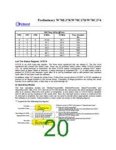
Bit Freq. (KHz) @Fosc
CR2
CR1
CR0
8 MHz
10 MHz
Fosc Divided
By
0
0
0
0
1
1
1
0
0
1
1
0
0
1
0
1
0
1
0
1
0
31.25
35.7
41.7
50.0
8.3
39.1
44.6
52.1
62.5
10.4
83.3
166.7
256
224
192
160
960
120
60
66.7
133.3
a-4) The Status Register, S1STA
S1STA is an 8-bit read-only register. The three least significant bits are always 0. The five most
significant bits contain the status code. There are 23 possible status codes. When S1STA contains
F8H, no serial interrupt is requested. All other S1STA values correspond to defined SIO1 states.
When each of these states is entered, a status interrupt is requested (SI = 1). A valid status code is
present in S1STA one machine cycle after SI is set by hardware and is still present one machine
cycle after SI has been reset by software.
In addition, state 00H stands for a Bus Error. A Bus Error occurs when a START or STOP condition is
present at an illegal position in the format frame. Examples of illegal positions are during the serial
transfer of an address byte, a data byte or an acknowledge bit.
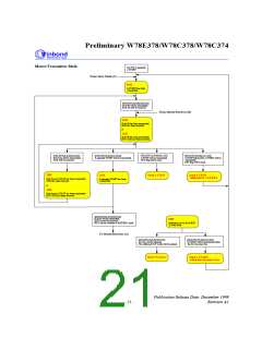
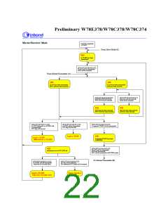
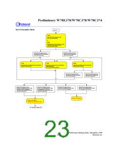
b) Operating Modes
The four operating modes are: Master/Transmitter, Master/Receiver, Slave/Transmitter and
Slave/Receiver. Bits STA, STO and AA in S1CON decide the next action the SIO1 hardware will take
after SI is cleared. When the next action is completed, a new status code in S1STA will be updated
and SI will be set by hardware in the same time. Now, the interrupt service routine is entered (if the
SI_interrupt is enabled), the new status code can be used to decide which appropriate service routine
the software is to branch. Data transfers in each mode are shown in the following figures.
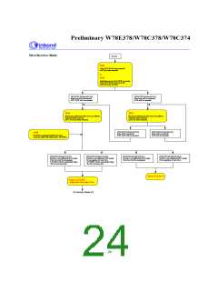
*** Legend for the following four figures:
Software's access to S1DAT with respect to "Expected next action":
Last state
08H
1) "Data byte will be transmitted":
A START has been
transmitted.
Last action is done
Software should load the data byte (to be transmitted) into S1DAT
before new S1CON setting is done.
2) "SLA+W (R) will be transmitted":
Next setting in S1CON
(STA,STO,SI,AA)=(0,0,0,X)
SLA+W will be transmitted;
ACK bit will be received.
Software should load the SLA+W/R (to be transmitted) into S1DAT
before new S1CON setting is done.
Expected next action
3) "Data byte will be received":
Software can read the received data byte from S1DAT
while a new state is entered.
New state
18H
SLA+W has been transmitted;
ACK has been received.
Next action is done
- 20 -

 WINBOND [ WINBOND ]