Preliminary W78E378/W78C378/W78C374
STA, the START Flag
STA = "1": When the STA bit is set to enter a master mode, the SIO1 hardware checks the status of
I2C bus and generates a START condition if the bus is free. If the bus is not free, then SIO1 waits for
a STOP condition and generates a START condition after a delay. If STA is set while SIO1 is already
in a master mode and one or more bytes are transmitted or received, SIO1 transmits a repeated
START condition. STA may be set at any time. STA may also be set when SIO1 is an addressed
slave.
STA = "0": When the STA bit is reset, no START condition or repeated START condition will be
generated.
STO, the STOP Flag
STO = "0": When the STO bit is set while SIO1 is in a master mode, a STOP condition is transmitted
to the I2C bus. When the STOP condition is detected on the bus, the SIO1 hardware clears the STO
flag. In a slave mode, the STO flag may be set to recover from an bus error condition. In this case, no
STOP condition is transmitted to the I2C bus. However, the SIO1 hardware behaves as if a STOP
condition has been received and switches to the defined not addressed slave receiver mode. The
STO flag is automatically cleared by hardware. If the STA and STO bits are both set, then a STOP
condition is transmitted to the I2C bus if SIO1 is in a master mode (in a slave mode, SIO1 generates
an internal STOP condition which is not transmitted). SIO1 then transmits a START condition.
SI, the Serial Interrupt Flag
SI = "1": When a new SIO1 state is present in the S1STA register, the SI flag is set by hardware, and,
if the EA and ES bits (in IE register) are both set, a serial interrupt is requested. The only state that
does not cause SI to be set is state F8H, which indicates that no relevant state information is
available. When SI is set, the low period of the serial clock on the SCL line is stretched, and the serial
transfer is suspended. A high level on the SCL line is unaffected by the serial interrupt flag. SI must
be cleared by software.
SI = "0": When the SI flag is reset, no serial interrupt is requested, and there is no stretching on the
serial clock on the SCL line.
AA, the Assert Acknowledge Flag
AA = "1": If the AA flag is set, an acknowledge (low level to SDA) will be returned during the
acknowledge clock pulse on the SCL line when: 1) The own slave address has been received. 2) A
data byte has been received while SIO1 is in the master receiver mode. 3) A data byte has been
received while SIO1 is in the addressed slave receiver mode.
AA = "0": If the AA flag is reset, a not acknowledge (high level to SDA) will be returned during the
acknowledge clock pulse on SCL when: 1) A data has been received while SIO1 is in the master
receiver mode. 2) A data byte has been received while SIO1 is in the addressed slave receiver mode.
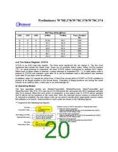
CR0, CR1 and CR2, the Clock Rate Bits
These three bits determine the serial clock frequency when SIO1 is in a master mode. It is not
important when SIO1 is in a slave mode. In the slave modes, SIO1 will automatically synchronize
with any clock frequency up to 100 KHz.
Publication Release Date: December 1999
- 19 -
Revision A1

 WINBOND [ WINBOND ]