VSC8601 Datasheet
Configuration
is no acknowledgement for three seconds, the VSC8601 device aborts its attempt to
connect to the EEPROM and reverts to its otherwise normal operating mode.
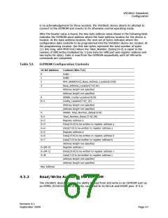
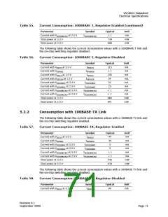
After the header value is found, the two-byte address value shown in the following table
indicates the EEPROM word address where the base address location for the device is
located. At the base address location, the next set of bytes indicates where the
configuration data contents to be programmed into the VSC8601 device are located. At
the programming location, the first two bytes represent the total number of bytes
(11 bits long, with MSB first) where the Total_Number_Bytes[10:0] is equal to the
number of SMI writes multiplied by 3 (one byte for SMI port and register address and
two bytes for data). Data is read from the EEPROM sequentially until all SMI write
commands are completed.
Table 52.
EEPROM Configuration Contents
10-bit Address
Content (Bits 7:0)
0
1
2
3
0xBD
0xBD
PHY_ADDR[4:0], Base_Address_Location[10:8]
Base_Address_Location[7:0] (K)
Address length not specified
Address length not specified
00000, Config Location[10:8]
Config_Location[7:0] (X)
K
K+1
Address length not specified
Address length not specified
00000, Total_Number_Bytes[10:8]
Total_Number_Bytes [7:0] (M)
Register address a
X
X+1
X+2
X+3
X+4
X+5
X+6
X+7
Data[15:8] to be written to register address a
Data[7:0] to be written to register address a
Register address b
Data[15:8] to be written to register address b
Data[7:0] to be written to register address b
Address length not specified
Register address x
X+(M–2)
X+(M–1)
X+M
Data[15:8] to be written to register address x
Data[7:0] to be written to register address x
Address length not specified
Address length not specified
Max Address
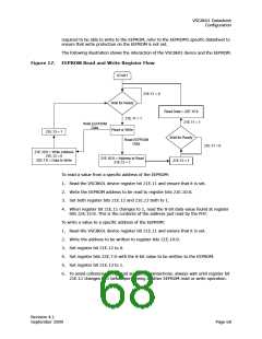
4.5.2
Read/Write Access to the EEPROM
The VSC8601 device also has the ability to read from and write to an EEPROM such as
an ATMEL AT24CXXX that is directly connected to its EECLK and EEDAT pins. If it is
Revision 4.1
September 2009
Page 67

 VITESSE [ VITESSE SEMICONDUCTOR CORPORATION ]