VSC6134
Datasheet
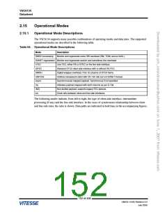
2.14.2
PRBS Checker Monitor Operation
The PRBS checker block monitors the input data for a valid pseudo-random binary sequence and detects
errors after it has synchronized to the input data.
The PRBS checker block I/O is shown in the following table.
Table 63. PRBS Checker Block I/O Description
Name
Direction
Function
clk
IN
IN
IN
IN
IN
IN
IN
IN
System clock
resetn
Active low system reset
Active low mpu reset
MPU clock
mpu_resetn
mpu_clk
mpu_wrena
mpu_rdena
mpu_corwn
sat_rollovern
MPU write enable
MPU read enable
MPU clear on read =0, write = 1
MPU saturation rollover control
0 = saturate and clear on read
1 = rollover
mpu_wdata[15:0]
prbschk_select
prbschk_rdata
prbschk_dtk
IN
MPU write data
IN
MPU block select
MPU read data
OUT
OUT
OUT
MPU data acknowledge
MPU interrupt
prbschk_int
The PRBS checker block is enabled by the PRBSCHK_ENA configuration bit. When enabled, the
PRBS checker loads the appropriate bits of the input data into the parallel LFSR state bits on every
clock cycle until a valid pseudo-random binary sequence is detected. The LFSR state bits feed into a
parallel pseudo-random generator whose output represents a pseudo-random data sequence to which the
incoming data can be compared. If the input bit sequence and the locally generated sequence match for
four consecutive clock cycles (256 bits), the checker goes into sync and transitions into the error
detection mode. The following figure shows the PRBS checker block diagram.
150 of 438
VMDS-10185 Revision 4.0
July 2006

 VITESSE [ VITESSE SEMICONDUCTOR CORPORATION ]