AN822
Vishay Siliconix
TABLE 1: EQIVALENT STEADY STATE PERFORMANCE
Package
SO-8
Single
20
TSSOP-8
TSOP-8
PPAK 1212
PPAK SO-8
Single Dual
1.8 5.5
Configuration
Dual
Single
Dual
Single
40
Dual
Single
Dual
40
52
83
90
2.4
5.5
Thermal Resiatance RthJC(C/W)
PowerPAK 1212
49.8 °C
Standard SO-8
Standard TSSOP-8
TSOP-6
85 °C
149 °C
125 °C
2.4 °C/W
20 °C/W
52 °C/W
40 °C/W
PC Board at 45 °C
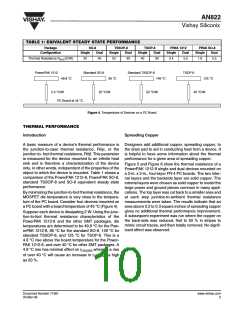
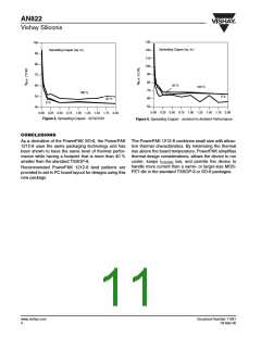
Figure 4. Temperature of Devices on a PC Board
THERMAL PERFORMANCE
Introduction
Spreading Copper
A basic measure of a device’s thermal performance is Designers add additional copper, spreading copper, to
the junction-to-case thermal resistance, Rθjc, or the the drain pad to aid in conducting heat from a device. It
junction to- foot thermal resistance, Rθjf. This parameter is helpful to have some information about the thermal
is measured for the device mounted to an infinite heat performance for a given area of spreading copper.
sink and is therefore a characterization of the device
only, in other words, independent of the properties of the
object to which the device is mounted. Table 1 shows a
comparison of the PowerPAK 1212-8, PowerPAK SO-8,
standard TSSOP-8 and SO-8 equivalent steady state
performance.
Figure 5 and Figure 6 show the thermal resistance of a
PowerPAK 1212-8 single and dual devices mounted on
a 2-in. x 2-in., four-layer FR-4 PC boards. The two inter-
nal layers and the backside layer are solid copper. The
internal layers were chosen as solid copper to model the
large power and ground planes common in many appli-
By minimizing the junction-to-foot thermal resistance, the cations. The top layer was cut back to a smaller area and
MOSFET die temperature is very close to the tempera- at each step junction-to-ambient thermal resistance
ture of the PC board. Consider four devices mounted on measurements were taken. The results indicate that an
a PC board with a board temperature of 45 °C (Figure 4)
.
area above 0.2 to 0.3 square inches of spreading copper
gives no additional thermal performance improvement.
A subsequent experiment was run where the copper on
the back-side was reduced, first to 50 % in stripes to
mimic circuit traces, and then totally removed. No signif-
icant effect was observed.
Suppose each device is dissipating 2 W. Using the junc-
tion-to-foot thermal resistance characteristics of the
PowerPAK 1212-8 and the other SMT packages, die
temperatures are determined to be 49.8 °C for the Pow-
erPAK 1212-8, 85 °C for the standard SO-8, 149 °C for
standard TSSOP-8, and 125 °C for TSOP-6. This is a
4.8 °C rise above the board temperature for the Power-
PAK 1212-8, and over 40 °C for other SMT packages. A
4.8 °C rise has minimal effect on r
whereas a rise
DS(ON)
of over 40 °C will cause an increase in r
as 20 %.
as high
DS(ON)
Document Number 71681
03-Mar-06
www.vishay.com
3

 VISHAY [ VISHAY ]