TMC8462 Datasheet • Document Revision V1.4 • 2018-May -09
176 / 204
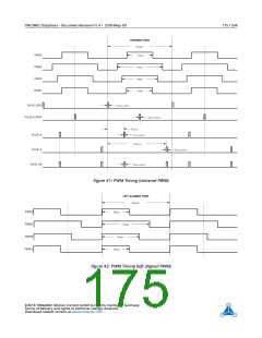
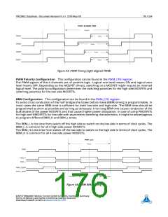
Figure 43: PWM Timing (right aligned PWM)
PWM Polarity Configuration This configuration can be found in the PWM_CFG register.
The PWM signals of the 4 channels are of positive logic. Logical one level means ON and logical zero
level means OFF. Depending on the MOSFET drivers, switching on a MOSFET might require an inverted
logical level. The polarity configuration determines the switching polarities for the high side MOSFETs and
switching polarities for the low side MOSFETs.
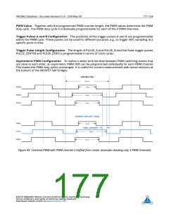
BBM Configuration This configuration can be found in the PWM_CFG register.
To avoid cross conduction of the half bridges the brake before make (BBM) timing is programmable. In
most cases the same BBM time is sufficient for both low side and high side. The BBM time should be
programmed as short as possible and as long as necessary. A too long BBM time causes conduction of the
bulk diodes of the power MOSFETs and that causes higher power dissipation. In case of using PMOSFETs
for high and NMOSFETs for low side with asymmetric switching characteristics, it might be advantageous
to program different BBM_H and BBM_L times.
The BBM_L is the time from switch off the high side to switch on the low side in terms of clock cycles. The
BBM_L is common for all 4 high side power MOSFETs.
The BBM_H is the time from switch off the low side to switch on the high side in terms of clock cycles. The
BBM_H is common for all 4 low side power MOSFETs.
Figure 44: PWM BBM Timing
©2018 TRINAMIC Motion Control GmbH & Co. KG, Hamburg, Germany
Terms of delivery and rights to technical change reserved.
Download newest version at www.trinamic.com

 TRINAMIC [ TRINAMIC MOTION CONTROL GMBH & CO. KG. ]