TMC6200 DATASHEET (Rev. 1.01 / 2018-NOV-15)
5
+VM
22n
100V
100n
16V
100n
+VM
CE
470n
VCP
VSA
CB
Gate Voltage
Regulator
12VOUT
Charge Pump
12VOUT
CU
HSU
U
100n
4.7µ
2.2µ
HS
LS
5VOUT
VOFS
5V Regulator
+VIO
IW
3.3V or 5V
I/O voltage
+
USENSE
LSU
VCC_IO
100n
OTP memory
VCP
3 Phase
Motor
CLK_IN
UH
CB
24MHz Oscillator
12VOUT
CV
pd
pd
pd
pd
pd
pd
B.Dwersteg, ©
TRINAMIC 2014
HSV
V
HS
LS
UL
Chopper Control
dual line LS+HS,
or single line
VOFS
VH
N
Break before
Make logic
IV
S
VL
+
VSENSE
LSV
(HS=polarity, LS=enable)
WH
WL
VCP
CB
Diagnostics
(Short circuit,
Temperature)
12VOUT
FAULT
CW
Diagnostic Output
5VOUT
HSW
W
HS
LS
CSN / IDRV0
SCK / IDRV1
SDI / AMPLx10
SDO / SINGLE
500k
Driver Strength [IDRV1 IDRV0]:
00: 0.5A 01: 0.5/1A, 10: 1A, 11: 1.5A
unused
+
WSENSE
LSW
Configuration
interface
250k
0: xH/xL individual gate control
1: xH=Polarity, xL=Enable control
IU
IV
5VOUT
1
0
pd
Current Sense
+VIO
RS
R1
R2
Use LMV641 or similar
Amplification=1+R2/R1
Enable
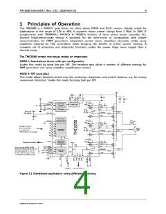
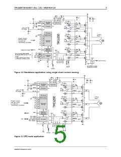
Figure 1.2 Standalone application using single shunt current sensing
+VM
22n
100V
100n
16V
100n
+VM
CE
470n
VCP
VSA
CB
Gate Voltage
Regulator
12VOUT
Charge Pump
12VOUT
CU
HSU
U
100n
4.7µ
2.2µ
HS
LS
5VOUT
VOFS
5V Regulator
+VIO
IW
3.3V or 5V
I/O voltage
+
USENSE
LSU
RS
VCC_IO
RP
100n
OTP memory
VCP
3 Phase
Motor
CLK_IN
UH
CB
24MHz Oscillator
12VOUT
CV
pd
pd
pd
pd
pd
pd
B.Dwersteg, ©
TRINAMIC 2014
HSV
V
HS
LS
UL
Chopper Control
dual line LS+HS,
or single line
VOFS
VH
N
Break before
Make logic
IV
S
VL
+
VSENSE
LSV
RS
(HS=polarity, LS=enable)
RP
WH
WL
VCP
CB
Diagnostics
(Short circuit,
Temperature)
12VOUT
FAULT
CW
5VOUT
HSW
W
HS
LS
CSN / IDRV0
SCK / IDRV1
SDI / AMPLx10
SDO / SINGLE
500k
+
WSENSE
LSW
RS
SPI
SPI interface
pd
RP
250k
IU
IV
+VIO
Enable
Current Sense
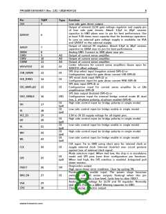
Figure 1.3 SPI mode application
www.trinamic.com

 TRINAMIC [ TRINAMIC MOTION CONTROL GMBH & CO. KG. ]