TMC6200 DATASHEET (Rev. 1.01 / 2018-NOV-15)
28
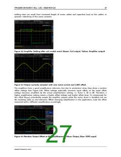
Attention
Each switching event on one of the motor outputs will cause a spike on the related current
measurement amplifier output. Its settling time of roughly 2µs to 4µs (depending on supply voltage
and sense resistors) should be blanked away by ignoring the output voltage during this time. This can
be ensured, when the external ADC samples the output synchronously with the chopper period.
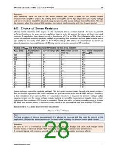
6.2 Choice of Sense Resistors
Choose sense resistors with regard to the maximum motor current desired. Be sure to provide
sufficient headroom for your current regulation loop in order to operate the motor at short time peak
currents. A regulation loop always needs a headroom of 25% to 50%. The following table shows a
choice of standard resistors (partially yielded by paralleling two resistors) and the peak currents which
can safely be measured with 1.65V or 2.5V Offset voltage. The choice of amplification is shown as
second parameter. An amplification of 20 only can be set when using the SPI interface.
CHOICE OF RSENSE AND AMPLIFICATION DEPENDING ON MAX. COIL CURRENT
RSENSE [mΩ]
Amplification
Current range [A] RMS motor current
limit [A]
Max. power dissipation
factor
10
5
5
5
10
10
5
5
10
5
10
10
20
10
20
of RSENSE [W]
0.05
0.15
0.23
0.3
0.16
0.23
0.45
0.67
0.38
0.9
150
150
100
75
33
25
50
33
15
25
10
5
0.7
1.3
2
2.6
3
0.5
1
1.5
2
2.2
3
4
4
3
6
6.5
8
4.5
5
6
10
20
20
40
50
7.5
15
15
30
37
0.56
1.1
0.56
2.3
2.5
2.5
1
1.4
Sense resistors should be carefully selected. The full motor current flows through the sense resistors.
Due to chopper operation the sense resistors see pulsed current from the MOSFET bridges. Therefore,
a low-inductance type such as film or composition resistors is required to prevent voltage spikes
causing ringing on the sense voltage inputs leading to unstable measurement results. Also, a low-
inductance, low-resistance PCB layout is essential. Please also refer to layout considerations in chapter
12. With low resistor values, it becomes more critical to do symmetrical and low resistive PCB traces.
CALCULATION OF PEAK SENSE RESISTOR POWER DISSIPATION
ꢄꢅ푆푀퐴푋 = 퐼ꢆꢂꢁ퐿2 ∗ 푅푆퐸푁푆퐸
Hint
For best precision of current measurement, it is advised to measure and fine tune the current in the
application. Choose the sense resistors to the next value covering the desired motor peak current.
Attention
Be sure to use a symmetrical sense resistor layout for each bridge and short and straight sense
resistor traces of identical length. Well matching sense resistors ensure best performance.
A compact layout with massive ground plane is best to avoid parasitic resistance effects.
www.trinamic.com

 TRINAMIC [ TRINAMIC MOTION CONTROL GMBH & CO. KG. ]