TMC6200 DATASHEET (Rev. 1.01 / 2018-NOV-15)
26
6 Current Sense Amplifiers
Integrated current sense amplifiers allow closed loop current regulation, as required for FOC control.
Measurement in series with the coil by principle is optimum for signal availability, because the current
will always pass the measurement shunt, independent of the actual chopper duty cycle and
independent of chopper phase. While this is a great benefit against foot point measurement, a series
measurement current amplifier is a complex component and may add considerable cost to a circuit.
With three current amplifiers integrated into the driver, overhead is kept minimum, and series shunt
sensing is available for the cost of bottom shunt measurement.
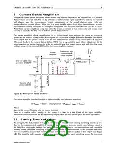
The sense amplifiers allow amplification of a bi-directional input voltage, by using an internally
generated or external offset voltage (see Figure 6.1). A positive voltage difference between the related
sense input and the phase output leads to the measurement output rising above VOFS. A negative
difference leads to the output falling below VOFS. The programmable gain allows adaptation to the
sense resistor and motor current, in order to optimally use the output swing and with this the input
voltage range of the external ADC tied to the sense amplifier outputs.
Differential high
Output
common mode
amplifier
range amplifier
5VOUT
PHASE
RSENSE
Internal 1.66V offset
generator 1/3x5VOUT
+
500k
250k
PHASE_SENSE
x1
x1
x2
x2
0: 05 x5
1: 10 x10
2: 10 x5
3: 20 x10
+VCC
10k
Optional offset
divider 1/2xVCC
10k
100n
Figure 6.1 Principle of sense amplifier
The sense amplifier transfer function is determined by the following equation:
퐶푈푅푃퐻퐴푆퐸 = 푉푂퐹ꢀ − 푎푚푝푙푖푓푖푐푎푡푖표푛 ∗ (푅푆퐸푁푆퐸 ∗ 퐼푃퐻퐴푆퐸 + 푉
)
ꢁ푁ꢂꢃ푆
Where
IPHASE is the current flowing into the motor terminal.
VINOFS is a random offset voltage in the range of a few to a few 10mV of the input amplifier.
Determine and compensate for by measuring output offset at zero current prior to motor operation.
6.1 Settling Time and Offset
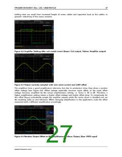
By principle, the disturbance of the coil series current measurement during switching events is low.
But, for the measurement amplifier, a switching event means a common mode signal change equal to
the height of the supply voltage. This switching temporarily disturbs the measurement and should be
blanked away. Therefore, sampling of the outputs should be synchronized to the chopper operation,
because switching slopes lead to disturbances and become visible as spikes at the output (see Figure
6.2). The amplifier will recover within a few microseconds after each switching event. An increased
www.trinamic.com

 TRINAMIC [ TRINAMIC MOTION CONTROL GMBH & CO. KG. ]