TMC6200 DATASHEET (Rev. 1.01 / 2018-NOV-15)
27
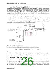
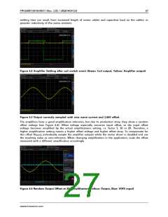
settling time can result from increased length of motor cables and capacitive load on the cables, or
parasitic inductivity of the sense resistors.
Figure 6.2 Amplifier Settling after coil switch event (Green: Coil output, Yellow: Amplifier output)
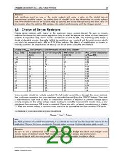
Figure 6.3 Output correctly sampled with sine wave current and 1.66V offset
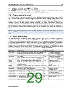
The amplifiers have a good amplification tolerance, but due to production stray, they show a random
offset voltage (see Figure 6.4). Offset voltage especially concerns input offset, as the input offset
voltage becomes amplified by the actual amplifications setting, i.e. factor 5, 10 or 20. Therefore, a
higher amplification setting means a higher offset voltage and higher offset stray. To compensate for
this offset (VINOFS), individually sample the amplifier outputs while the motor driver is disabled and use
the resulting value as zero-reference. When changing amplification in the application, scale the offset
measured with a different amplification accordingly.
Figure 6.4 Random Output Offset at 20x amplification (Yellow: Output, Blue: VOFS input)
www.trinamic.com

 TRINAMIC [ TRINAMIC MOTION CONTROL GMBH & CO. KG. ]