TMC5130A DATASHEET (Rev. 1.14 / 2017-MAY-15)
66
9 Analog Current Control AIN
When a high flexibility of the output current scaling is desired, the analog input of the driver can be
enabled for current control, rather than choosing a different set of sense resistors or scaling down the
run current via IRUN parameter. This way, a simple voltage divider can be used for the adaptation of
a board to different motors.
AIN SCALES THE MOTOR CURRENT
The TMC5130A provides an internal reference voltage for current control, directly derived from the
5VOUT supply output. Alternatively, an external reference voltage can be used. This reference voltage
becomes scaled down for the chopper comparators. The chopper comparators compare the voltages
on BRA and BRB to the scaled reference voltage for current regulation. When I_scale_analog in GCONF
is enabled, the external voltage on AIN is amplified and filtered and becomes used as reference
voltage. A voltage of 2.5V (or any voltage between 2.5V and 5V) gives the same current scaling as the
internal reference voltage. A voltage between 0V and 2.5V linearly scales the current between 0 and
the current scaling defined by the sense resistor setting. It is not advised to work with reference
voltages below about 0.5V to 1V, because relative analog noise caused by digital circuitry has an
increased impact on the chopper precision at low AIN voltages. For best precision, choose the sense
resistors in a way that the desired maximum current is reached with AIN in the range 2V to 2.4V. Be
sure to optimize the chopper settings for the normal run current of the motor.
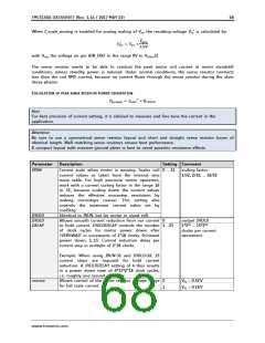
DRIVING AIN
The easiest way to provide a voltage to AIN is to use a voltage divider from a stable supply voltage
or a microcontroller’s DAC output. A PWM signal can also be used for current control. The PWM
becomes transformed to an analog voltage using an additional R/C low-pass at the AIN pin. The PWM
duty cycle controls the analog voltage. Choose the R and C values to form a low pass with a corner
frequency of several milliseconds while using PWM frequencies well above 10 kHz. AIN additionally
provides an internal low-pass filter with 3.5kHz bandwidth. When a precise reference voltage is
available (e.g. from TL431A), the precision of the motor current regulation can be improved when
compared to the internal voltage reference.
Hint
Using a low reference voltage (e.g. below 1V), for adaptation of a high current driver to a low current
motor will lead to reduced analog performance. Adapting the sense resistors to fit the desired motor
current gives a better result.
2.5V
precision
reference
1-2.4V for fixed
current scaling
0-2.4V for
current scaling
0-2.4V for
current scaling
Digital
current
control
PWM output
of µC with
>20kHz
5VOUT or precise
reference voltage
8 Bit DAC
R1
22k
R2
R3
1µ
R1+R2»10K
Optional
digital
control
BC847
100k
DAC Reference
IREF
DAC Reference
IREF
DAC Reference
IREF
Fixed resistor divider to set current scale
(use external reference for enhanced precision)
Precision current scaler
Simple PWM based current scaler
Figure 9.1 Scaling the motor current using the analog input
www.trinamic.com

 TRINAMIC [ TRINAMIC MOTION CONTROL GMBH & CO. KG. ]