TMC5130A DATASHEET (Rev. 1.14 / 2017-MAY-15)
69
11 Internal Sense Resistors
The TMC5130A provides the option to eliminate external sense resistors. In this mode the external
sense resistors become omitted (shorted) and the internal on-resistance of the power MOSFETs is
used for current measurement (see Figure 3.3). As MOSFETs are both, temperature dependent and
subject to production stray, a tiny external resistor connected from +5VOUT to AIN/IREF is used to
provide a precise absolute current reference. This resistor converts the 5V voltage into a reference
current. Be sure to directly attach BRA and BRB pins to GND in this mode near the IC package. The
mode is enabled by setting internal_Rsense in GCONF.
COMPARING INTERNAL SENSE RESISTORS VS. SENSE RESISTORS
Item
Ease of use
Cost
Current precision
Current Range
Recommended
Recommended
chopper
Internal Sense Resistors
Set internal_Rsense first
(+) Save cost for sense resistors
Slightly reduced
External Sense Resistors
(+) Default
(+) Good
50mA to 1.4A RMS
200mA RMS to 1.2A RMS
stealthChop,
spreadCycle shows slightly
reduced performance at >1A
stealthChop or spreadCycle
While the RDSon based measurements bring benefits concerning cost and size of the driver, it gives
slightly less precise coil current regulation when compared to external sense resistors. The internal
sense resistors have a certain temperature dependence, which is automatically compensated by the
driver IC. However, for high current motors, a temperature gradient between the ICs internal sense
resistors and the compensation circuit will lead to an initial current overshoot of some 10% during
driver IC heat up. While this phenomenon shows for roughly a second, it might even be beneficial to
enable increased torque during initial motor acceleration.
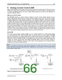
PRINCIPLE OF OPERATION
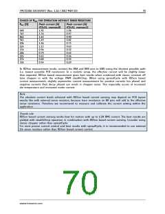
A reference current into the AIN/IREF pin is used as reference for the motor current. In order to
realize a certain current, a single resistor (RREF) can be connected between 5VOUT and AIN/IREF (pls.
refer the table for the choice of the resistor). AIN/IREF input resistance is about 1kOhm. The resulting
current into AIN/IREF is amplified 3000 times. Thus, a current of 0.5mA yields a motor current of 1.5A
peak. For calculation of the reference resistor, the internal resistance of VREF needs to be considered
additionally.
When using reference currents above 0.5mA resulting in higher theoretical current settings of up to
2A, the resulting current decreases linearly when chip temperature exceeds a certain maximum
temperature. For a 2A setting it decreases from 2A at up to 100°C down to about 1.5A at 150°C. The
resulting curve limits the maximum current setting in this mode. For calculation of the reference
resistor, the internal resistance of AIN/RREF needs to be considered additionally.
vsense=1 allows a lower peak current setting of about 55% of the value yielded with vsense=0 (as
specified by VSRTH / VSRTL). For fine tuning use the current scale CS.
www.trinamic.com

 TRINAMIC [ TRINAMIC MOTION CONTROL GMBH & CO. KG. ]