TMC5130A DATASHEET (Rev. 1.14 / 2017-MAY-15)
67
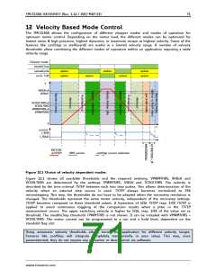
10 Selecting Sense Resistors
Set the desired maximum motor current by selecting an appropriate value for the sense resistor. The
following table shows the RMS current values which can be reached using standard resistors and
motor types fitting without additional motor current scaling.
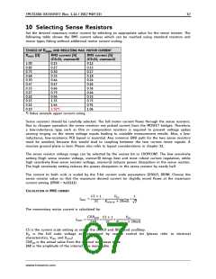
CHOICE OF RSENSE AND RESULTING MAX. MOTOR CURRENT
RSENSE [Ω]
RMS current [A]
RMS current [A]
(CS=31, vsense=0)
(CS=31, vsense=1)
1.00
0.82
0.75
0.68
0.50
0.47
0.33
0.27
0.22
0.15
0.12
0.10
0.23
0.27
0.30
0.33
0.44
0.47
0.66
0.79
0.96
1.35
1.64
1.92*)
0.12
0.15
0.17
0.18
0.24
0.26
0.36
0.44
0.53
0.75
0.91
1.06
*) Value exceeds upper current rating.
Sense resistors should be carefully selected. The full motor current flows through the sense resistors.
Due to chopper operation the sense resistors see pulsed current from the MOSFET bridges. Therefore,
a low-inductance type such as film or composition resistors is required to prevent voltage spikes
causing ringing on the sense voltage inputs leading to unstable measurement results. Also, a low-
inductance, low-resistance PCB layout is essential. Any common GND path for the two sense resistors
must be avoided, because this would lead to coupling between the two current sense signals. A
massive ground plane is best. Please also refer to layout considerations in chapter 31.
The sense resistor voltage range can be selected by the vsense bit in CHOPCONF. The low sensitivity
setting (high sense resistor voltage, vsense=0) brings best and most robust current regulation, while
high sensitivity (low sense resistor voltage, vsense=1) reduces power dissipation in the sense resistor.
The high sensitivity setting reduces the power dissipation in the sense resistor by nearly half.
The current to both coils is scaled by the 5-bit current scale parameters (IHOLD, IRUN). Choose the
sense resistor value so that the maximum desired current (or slightly more) flows at the maximum
current setting (IRUN = %11111).
CALCULATION OF RMS CURRENT
퐶푆 + ꢃ
3ꢀ
푉퐹ꢒ
ꢃ
퐼ꢠ푀ꢒ
=
∗
∗
푅ꢒꢓ푁ꢒꢓ + ꢀꢄꢍΩ
ꢀ
√
The momentary motor current is calculated by:
퐶푈푅퐴/퐵
퐶푆 + ꢃ
푉
퐹ꢒ
퐼푀푂푇
=
∗
∗
ꢀ4ꢁ
3ꢀ
푅ꢒꢓ푁ꢒꢓ + ꢀꢄꢍΩ
CS is the current scale setting as set by the IHOLD and IRUN and coolStep.
VFS is the full scale voltage as determined by vsense control bit (please refer to electrical
characteristics, VSRTL and VSRTH).
CURA/B is the actual value from the internal sine wave table.
248 is the amplitude of the internal sine wave table.
www.trinamic.com

 TRINAMIC [ TRINAMIC MOTION CONTROL GMBH & CO. KG. ]